

CMOS Optical Preamplifier Design Using Graphical Circuit Analysis
CMOS Optical Preamplifier Design Using Graphical Circuit Analysis
CMOS Optical Preamplifier Design Using Graphical Circuit Analysis

You also want an ePaper? Increase the reach of your titles
YUMPU automatically turns print PDFs into web optimized ePapers that Google loves.
4.3 DPI/SFG: Combining DPI <strong>Analysis</strong> and Signal-Flow Graphs 84<br />
4.3 DPI/SFG: COMBINING DPI ANALYSIS AND SIGNAL-FLOW GRAPHS<br />
DPI/SFG analysis combines driving-point impedance analysis and signal-flow<br />
graphs. DPI relations are of the form<br />
vn = Z DPn × I SCn<br />
(4.7)<br />
and they are naturally represented in signal-flow graphs because they represent a<br />
cause-and-effect relationship. DPI/SFG analysis follows the same procedure out-<br />
lined in Section 4.2.1 for DPI analysis. There are certain characteristics that signal-<br />
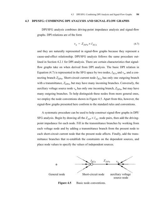
flow graphs take on when derived from DPI analysis. The basic DPI relation in<br />
Equation (4.7) is represented in the SFG space by two nodes, I SCn and v n , and a con-<br />
necting branch Z DPn . Short-circuit current node I SCn has only one outgoing branch<br />
with a transmittance, Z DPn , but may have many incoming branches. Conversely, the<br />
auxiliary voltage source node v n has only one incoming branch, Z DPn , but may have<br />
many outgoing branches. To help distinguish these nodes from more general ones,<br />
we employ the node conventions shown in Figure 4.5. Apart from this, however, the<br />
signal-flow graphs presented here conform to the standard rules and conventions.<br />
A systematic procedure can be used to help construct signal-flow graphs in DPI/<br />
SFG analysis. Begin by drawing all the Z DP × I SC node pairs, then add the drivingpoint<br />
impedance for each node. Fill in the transmittance branches by working from<br />
each voltage node and by adding a transmittance branch from the present node to<br />
each short-circuit current node that the present node affects. Finally, add the trans-<br />
mittance branches that re-establish the constraints on the dependent sources, and<br />
place node values to specify the values of independent sources.<br />
General node<br />
I SCn Z DPn vn<br />
Figure 4.5 Basic node conventions.<br />
Short-circuit node auxiliary voltage<br />
source node


