

CMOS Optical Preamplifier Design Using Graphical Circuit Analysis
CMOS Optical Preamplifier Design Using Graphical Circuit Analysis
CMOS Optical Preamplifier Design Using Graphical Circuit Analysis

Create successful ePaper yourself
Turn your PDF publications into a flip-book with our unique Google optimized e-Paper software.
3.3 A Low-Voltage Transimpedance Amplifier 62<br />
of the amplifier. In practice, we need to derive a set of relations that embody the<br />
essence of the circuit and characterize its design trade-offs. DPI/SFG analysis has<br />
the potential to fulfill this requirement. The method is presented in Chapter 4, and<br />
its application to the low-voltage transimpedance amplifier is presented in Chapter<br />
5. Before proceeding, however, we need to conclude this section by discussing one<br />
final design challenge for the low-voltage transimpedance amplifier: the implemen-<br />
tation of the feedback resistor.<br />
3.3.1 Dynamic Gate Biasing<br />
Transimpedance (dB ohms)<br />
80<br />
70<br />
60<br />
50<br />
40<br />
30<br />
20<br />
10<br />
10 0<br />
0<br />
10 1<br />
Frequency (MHz)<br />
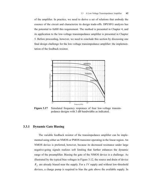
Figure 3.17 Simulated frequency responses of four low-voltage transimpedance<br />
designs with 3 dB bandwidths as indicated.<br />
The variable feedback resistor of the transimpedance amplifier can be imple-<br />
mented using either an NMOS or PMOS transistor operating in the linear region. An<br />
NMOS device is preferred, however, because its decreased resistance under large<br />
negative-going signals realizes soft limiting that further enhances the dynamic<br />
range of the preamplifier. Biasing the gate of the NMOS device is a challenge. As<br />
illustrated by the typical bias voltages in Figure 3.12, the source and drain of device<br />
R f<br />
60MHz<br />
80MHz<br />
70MHz<br />
are already biased near the supply. For a 1V supply and without low-threshold<br />
devices, a charge pump is required to bias the gate above the available supply. In<br />
10 2<br />
160MHz<br />
10 3


