

Research Directory of the Brandenburg University of Applied Sciences
Research Directory of the Brandenburg University of Applied Sciences
Research Directory of the Brandenburg University of Applied Sciences

Sie wollen auch ein ePaper? Erhöhen Sie die Reichweite Ihrer Titel.
YUMPU macht aus Druck-PDFs automatisch weboptimierte ePaper, die Google liebt.
<strong>the</strong>se detectors respond much<br />
faster. The detectors are connected<br />
to a read out circuit<br />
(ROIC) for snapshot integration.<br />
The photocurrent generated<br />
by <strong>the</strong> incident photon flux<br />
will be stored in a capacitor<br />
during a user selectable integration<br />
time (or exposure<br />
time). This integration time<br />
will determine <strong>the</strong> time resolution<br />
<strong>of</strong> <strong>the</strong> camera. For <strong>the</strong><br />
SC6000 variable integration<br />
time settings from 9 μs to full<br />
frame time are possible. For<br />
<strong>the</strong> experiment with <strong>the</strong> falling<br />
ball an integration time <strong>of</strong> 1<br />
ms was used, see Fig. 3.13. No<br />
blurring <strong>of</strong> <strong>the</strong> image <strong>of</strong> <strong>the</strong><br />
ball is observed and <strong>the</strong> temperature<br />
<strong>of</strong> <strong>the</strong> ball can be correctly<br />
determined over <strong>the</strong><br />
whole falling distance.<br />
b) Spatial resolution<br />
The spatial resolution <strong>of</strong> <strong>the</strong> <strong>the</strong>rmal imaging system<br />
determines <strong>the</strong> minimum size <strong>of</strong> objects which can be<br />
analyzed. Fig. 3.16 demonstrates that different camera<br />
systems lead to different results when studying miniaturized<br />
objects. A <strong>the</strong>rmal emitter with an area <strong>of</strong> 2.1<br />
mm x 1.8 mm was analyzed with a 320 x 240 pixels MW<br />
THV 550 camera and <strong>the</strong> 640 x 512 pixels SC6000<br />
camera with different optics.<br />
Obviously <strong>the</strong> SC6000 microscope<br />
optics provides <strong>the</strong> best spatial resolution.<br />
As will be shown below a detailed<br />
analysis <strong>of</strong> this structure is only<br />
possible using <strong>the</strong> SC6000 with<br />
microscope optics.<br />
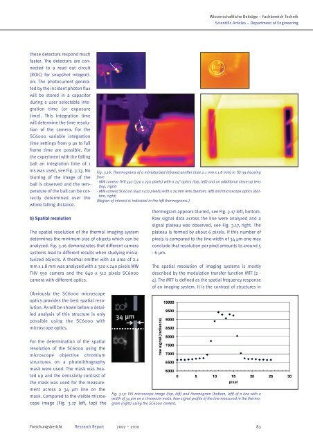
For <strong>the</strong> determination <strong>of</strong> <strong>the</strong> spatial<br />
resolution <strong>of</strong> <strong>the</strong> SC6000 using <strong>the</strong><br />
microscope objective chromium<br />
structures on a photolithography<br />
mask were used. The mask was heated<br />
up and <strong>the</strong> emissivity contrast <strong>of</strong><br />
<strong>the</strong> mask was used for <strong>the</strong> measurement<br />
across a 34 μm line on <strong>the</strong><br />
mask. Compared to <strong>the</strong> visible microscope<br />
image (Fig. 3.17 left, top) <strong>the</strong><br />
Wissenschaftliche Beiträge – Fachbereich Technik<br />
Scientific Articles – Department <strong>of</strong> Engineering<br />
Fig. 3.16: Thermograms <strong>of</strong> a miniaturized infrared emitter (size 2.1 mm x 1.8 mm) in TO-39 housing<br />
from<br />
- MW camera THV 550 (320 x 240 pixels) with a 24° optics (top, left) and an additional close-up lens<br />
(top, right)<br />
- MW camera SC6000 (640 x 512 pixels) with a 25 mm lens (bottom, left) and microscope optics (bottom,<br />
right)<br />
(Region <strong>of</strong> interest is indicated in <strong>the</strong> left <strong>the</strong>rmograms.)<br />
<strong>the</strong>rmogram appears blurred, see Fig. 3.17 left, bottom.<br />
Raw signal data across <strong>the</strong> line were analyzed and a<br />
signal plateau was observed, see Fig. 3.17, right. The<br />
plateau is formed by about 6 pixels. If this number <strong>of</strong><br />
pixels is compared to <strong>the</strong> line width <strong>of</strong> 34 μm one may<br />
conclude that resolution per pixel amounts to around 5<br />
- 6 μm.<br />
The spatial resolution <strong>of</strong> imaging systems is mostly<br />
described by <strong>the</strong> modulation transfer function MTF [2 -<br />
4]. The MTF is defined as <strong>the</strong> spatial frequency response<br />
<strong>of</strong> an imaging system. It is <strong>the</strong> contrast <strong>of</strong> structures in<br />
Fig. 3.17: VIS microscope image (top, left) and <strong>the</strong>rmogram (bottom, left) <strong>of</strong> a line with a<br />
width <strong>of</strong> 34 μm on a chromium mask. Raw signal pr<strong>of</strong>ile <strong>of</strong> <strong>the</strong> line measured in <strong>the</strong> <strong>the</strong>rmogram<br />
(right) using <strong>the</strong> SC6000 camera.<br />
Forschungsbericht <strong>Research</strong> Report 2007 – 2010 83