AFI 11-2C-130v3 - BITS
AFI 11-2C-130v3 - BITS
AFI 11-2C-130v3 - BITS
Create successful ePaper yourself
Turn your PDF publications into a flip-book with our unique Google optimized e-Paper software.
174 <strong>AFI</strong><strong>11</strong>-<strong>2C</strong>-130V3 23 APRIL 2012<br />
power receptacle of the disabled aircraft<br />
12.10.3.1.1.8. Accomplish failed battery relay procedure. (See paragraph<br />
12.10.3.5)<br />
12.10.3.1.1.9. When battery relay is closed and APU generator is powering TR<br />
units on the aircraft supplying DC power to the ESS and Main DC buses, remove<br />
jumper cables and continue with STARTING ENGINES CHECKLIST. NOTE:<br />
It is recommended to start at least one engine and have its generator on line before<br />
disconnecting power cables.<br />
12.10.3.1.2. DC Power Without Usable Aircraft Battery Or Spare Aircraft<br />
12.10.3.1.2.1. Obtain two 12 volt or one 24 volt battery and jumper cables, or<br />
suitable heavy duty cable, modified as required. (DC cargo winch cable may be<br />
used.)<br />
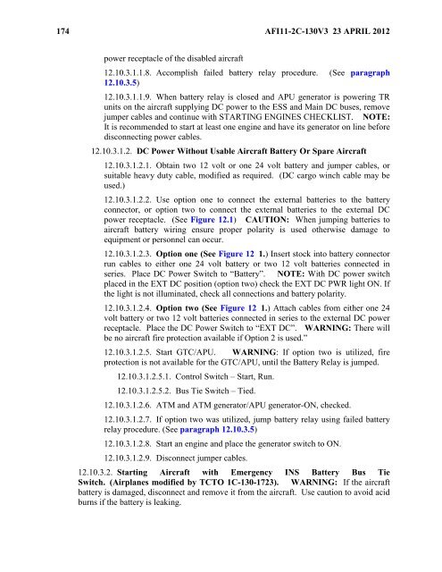
12.10.3.1.2.2. Use option one to connect the external batteries to the battery<br />
connector, or option two to connect the external batteries to the external DC<br />
power receptacle. (See Figure 12.1) CAUTION: When jumping batteries to<br />
aircraft battery wiring ensure proper polarity is used otherwise damage to<br />
equipment or personnel can occur.<br />
12.10.3.1.2.3. Option one (See Figure 12 1.) Insert stock into battery connector<br />
run cables to either one 24 volt battery or two 12 volt batteries connected in<br />
series. Place DC Power Switch to ―Battery‖. NOTE: With DC power switch<br />
placed in the EXT DC position (option two) check the EXT DC PWR light ON. If<br />
the light is not illuminated, check all connections and battery polarity.<br />
12.10.3.1.2.4. Option two (See Figure 12 1.) Attach cables from either one 24<br />
volt battery or two 12 volt batteries connected in series to the external DC power<br />
receptacle. Place the DC Power Switch to ―EXT DC‖. WARNING: There will<br />
be no aircraft fire protection available if Option 2 is used.‖<br />
12.10.3.1.2.5. Start GTC/APU. WARNING: If option two is utilized, fire<br />
protection is not available for the GTC/APU, until the Battery Relay is jumped.<br />
12.10.3.1.2.5.1. Control Switch – Start, Run.<br />
12.10.3.1.2.5.2. Bus Tie Switch – Tied.<br />
12.10.3.1.2.6. ATM and ATM generator/APU generator-ON, checked.<br />
12.10.3.1.2.7. If option two was utilized, jump battery relay using failed battery<br />
relay procedure. (See paragraph 12.10.3.5)<br />
12.10.3.1.2.8. Start an engine and place the generator switch to ON.<br />
12.10.3.1.2.9. Disconnect jumper cables.<br />
12.10.3.2. Starting Aircraft with Emergency INS Battery Bus Tie<br />
Switch. (Airplanes modified by TCTO 1C-130-1723). WARNING: If the aircraft<br />
battery is damaged, disconnect and remove it from the aircraft. Use caution to avoid acid<br />
burns if the battery is leaking.


