- Page 1 and 2: 1. Overview and Features Under deve
- Page 3 and 4: Under development (13) Standby mode
- Page 5 and 6: 2. Pin Layout and Pin Functions Und
- Page 7 and 8: Pin No. Under development Table 2.1
- Page 9 and 10: Type Function Function/ BOOT Functi
- Page 11 and 12: Type Function/ Debug Function # of
- Page 13 and 14: 2.3 Pin Names and Power Supply Pins
- Page 15 and 16: 4. Memory map 4.1 Memory map 0x4008
- Page 17 and 18: 0x4008 FFFF 0x4000 0000 0x2000 1FFF
- Page 19 and 20: X1 X2 XT1 XT2 5.2.2 Clock System Bl
- Page 21 and 22: SYSCR0 SYSCR1 SYSCR2 5.3.2 Detailed
- Page 23 and 24: STBYCR0 STBYCR1 STBYCR2 5.3.2.3 Sta
- Page 25 and 26: CKSEL 5.3.2.5 System Clock Selectio
- Page 27 and 28: 5.4.2 Main System Clock External os
- Page 29 and 30: 5.4.4 System Clock Pin Output Funct
- Page 31 and 32: 5.8.1 IDLE Mode Under development T
- Page 33 and 34: Under development 5.8.4 Low power C
- Page 35 and 36: 5.8.7 Warm-up Under development TMP
- Page 37 and 38: Under development 5.8.8.3 Transitio
- Page 39 and 40: 6.2.2 Generation Under development
- Page 41 and 42: Under development Table 6-1 List of
- Page 43 and 44: Under development TMPM330 (rev0.4)
- Page 45 and 46: Under development TMPM330 (rev0.4)
- Page 47 and 48: 6.3.6 Interrupt Service Routine Und
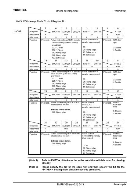
- Page 49: 6.4.2 CG Interrupt Mode Control Reg
- Page 53 and 54: Under development TMPM330 (rev0.4)
- Page 55 and 56: 6.4.7 NMI Flag Register Under devel
- Page 57 and 58: 7 Input/Output Ports 7.1 Port regis
- Page 59 and 60: Under development Port A input enab
- Page 61 and 62: 7.1.3 Port C (PC0~PC3) Under develo
- Page 63 and 64: 7.1.5 Port E (PE0~PE6) Under develo
- Page 65 and 66: 7.1.6 Port F (PF0~PF7) Under develo
- Page 67 and 68: 7.1.7 Port G (PG0~PG7) Under develo
- Page 69 and 70: 7.1.8 Port H (PH0~PH7) Under develo
- Page 71 and 72: 7.1.10 Port J (PJ0~PJ7) Under devel
- Page 73 and 74: Under development Port K input enab
- Page 75 and 76: 8.2 Differences in the Specificatio
- Page 77 and 78: Configuration Under development TMP
- Page 79 and 80: Registers 8.2.1 TMRB registers Spec
- Page 81 and 82: Under development 8.2.1.1 TMRBn ena
- Page 83 and 84: Under development 8.2.1.3 TMRB cont
- Page 85 and 86: Under development 8.2.1.5 TMRB flip
- Page 87 and 88: TBnIM (0x4001_0xx8) Under developme
- Page 89 and 90: Under development 8.2.1.9 TMRB time
- Page 91 and 92: Under development 8.3 Description o
- Page 93 and 94: Under development TMPM330 (rev 0.4)
- Page 95 and 96: Under development TMPM330 (rev 0.4)
- Page 97 and 98: • Register setting Under developm
- Page 99 and 100: Under development 8.4 Description o
- Page 101 and 102:
Under development The block diagram
- Page 103 and 104:
Under development 8.6 Applications
- Page 105 and 106:
Prescaler output clock TB5IN0 pin i
- Page 107 and 108:
9 Serial Channel (SIO) 9.1 Features
- Page 109 and 110:
• Mode 0 (I/O Interface mode) /LS
- Page 111 and 112:
Under development 9.3 Operation of
- Page 113 and 114:
Under development (Note 1) The pres
- Page 115 and 116:
Under development (Note 1) The pres
- Page 117 and 118:
• Example baud rate setting: Unde
- Page 119 and 120:
fc [MHz] Under development Table 9-
- Page 121 and 122:
Under development TMPM330 (rev 0.4)
- Page 123 and 124:
Under development I/O interface mo
- Page 125 and 126:
• Handshake function Data write t
- Page 127 and 128:
9.3.10 Transmit FIFO Buffer Under d
- Page 129 and 130:
9.3.12 Parity Control Circuit 9.3.1
- Page 131 and 132:
Under development 9.3.17 Configurat
- Page 133 and 134:
Under development 9.4 Register Desc
- Page 135 and 136:
9.4.4 Mode control register 0 SC0MO
- Page 137 and 138:
Under development : This is a statu
- Page 139 and 140:
Under development TMPM330 (rev 0.4)
- Page 141 and 142:
9.4.10 TX FIFO configuration regist
- Page 143 and 144:
9.5 Operation in Each Mode 9.5.1 Mo
- Page 145 and 146:
SCLK input mode Under development T
- Page 147 and 148:
Receiving data SCLK output mode Rec
- Page 149 and 150:
Transmit and receive (full-duplex)
- Page 151 and 152:
SCLK input mode Under development T
- Page 153 and 154:
9.5.2 Mode 1 (7-bit UART Mode) Unde
- Page 155 and 156:
9.5.4 Mode 3 (9-bit UART) Under dev
- Page 157 and 158:
10. Serial Bus Interface (SBI) Chan
- Page 159 and 160:
10.2 Control Under development TMPM
- Page 161 and 162:
SBIxCR0 10.4 Control Registers in t
- Page 163 and 164:
Under development TMPM330 (rev 0.4)
- Page 165 and 166:
Under development Table 10-1 Base C
- Page 167 and 168:
SBIxBR0 bit Symbol I2SBI0 Under dev
- Page 169 and 170:
10.5 Control in the I 2 C Bus Mode
- Page 171 and 172:
Under development 10.5.6 Configurin
- Page 173 and 174:
Master A Master B Under development
- Page 175 and 176:
Under development 10.6 Data Transfe
- Page 177 and 178:
SCL pin Write to SBIxDBR SDA pin I
- Page 179 and 180:
Slave mode ( = “0”) Under devel
- Page 181 and 182:
10.6.4 Generating the Stop Conditio
- Page 183 and 184:
Under development 10.7 Control in t
- Page 185 and 186:
SBIxDBR SBIxCR2 Under development S
- Page 187 and 188:
10.7.1 Serial Clock SCK pin output
- Page 189 and 190:
10.7.2 Transfer Modes Under develop
- Page 191 and 192:
SCK pin SIOF SO pin bit 6 Under dev
- Page 193 and 194:
SCK pin (output) SO pin SI pin IN
- Page 195 and 196:
11.2 Registers 11.2.1 Control Regis
- Page 197 and 198:
Under development 11.2.5 Software R
- Page 199 and 200:
Under development 11.2.7 Receive Bu
- Page 201 and 202:
Under development TMPM330 (rev0.4)1
- Page 203 and 204:
Under development 11.2.10 Receive C
- Page 205 and 206:
Under development 11.2.11 Transmit
- Page 207 and 208:
Under development 11.2.13 Transmit
- Page 209 and 210:
Under development 11.2.14 Receive I
- Page 211 and 212:
11.3 Operations 11.3.1 Reception 11
- Page 213 and 214:
(3) Cycle Error Under development C
- Page 215 and 216:
(10) Waveform Error Detection Under
- Page 217 and 218:
11.3.1.6 Data Sampling Point Under
- Page 219 and 220:
11.3.1.8 Detecting Error Interrupt
- Page 221 and 222:
Under development TMPM330 (rev0.4)1
- Page 223 and 224:
11.3.2.2 Preconfiguration Under dev
- Page 225 and 226:
11.3.2.3 Starting Transmission Unde
- Page 227 and 228:
(2) ACK error Under development TMP
- Page 229 and 230:
Under development 12 Remote control
- Page 231 and 232:
Under development 12.2.2 Remote Con
- Page 233 and 234:
Under development 12.2.5 Remote Con
- Page 235 and 236:
(Note) Under development When you c
- Page 237 and 238:
Under development 12.2.9 Remote Con
- Page 239 and 240:
Under development 12.2.11 Remote Co
- Page 241 and 242:
12.3.1.3 Preparation Under developm
- Page 243 and 244:
(3) Settings of Data Bit Determinat
- Page 245 and 246:
12.3.1.6 Reception Completion Under
- Page 247 and 248:
Under development 12.3.1.8 Receivin
- Page 249 and 250:
Remote control signal waveform (inp
- Page 251 and 252:
Remote control signal in phase meth
- Page 253 and 254:
13.1 Registers Under development Th
- Page 255 and 256:
ADMOD1 Under development A/D Mode C
- Page 257 and 258:
ADMOD3 Under development A/D Mode C
- Page 259 and 260:
ADMOD4 Under development A/D Mode C
- Page 261 and 262:
ADREG2AL ADREG2AH ADREG3BL ADREG3BH
- Page 263 and 264:
ADREG6EL ADREG6EL ADREG6EL ADREG6EL
- Page 265 and 266:
ADCMP0L ADCMP0H ADCMP1L ADCMP1H Und
- Page 267 and 268:
13.4 Description of Operations 13.4
- Page 269 and 270:
Under development TMPM330 (rev 0.4)
- Page 271 and 272:
Under development 3. Fixed channel
- Page 273 and 274:
13.4.5 High-priority Conversion Mod
- Page 275 and 276:
Under development 14. Watchdog Time
- Page 277 and 278:
14.3 Control Registers Under develo
- Page 279 and 280:
14.4 Control Register Under develop
- Page 281 and 282:
15.3 Control Register Under develop
- Page 283 and 284:
MINR Under development (2) Minute c
- Page 285 and 286:
DAYR DATER Under development (4) Da
- Page 287 and 288:
YEARR YEARR Under development (8) Y
- Page 289 and 290:
15.5 Operational description (1) Re
- Page 291 and 292:
3. Disabling the clock Under develo
- Page 293 and 294:
(2) 1Hz clock Under development TMP
- Page 295 and 296:
16.1 Addresses [1] Port [1/4] ADR
- Page 297 and 298:
[1] Port 3/4] ADR Register name AD
- Page 299 and 300:
[2] 16-bit timer [1/4] ADR Registe
- Page 301 and 302:
[2] 16-bit timer [3/4] ADR Registe
- Page 303 and 304:
Under development [3] Serial bus in
- Page 305 and 306:
[5] 10-bit A/D converter (A/DC) ADR
- Page 307 and 308:
[10] Remote control signal preproce
- Page 309 and 310:
Under development JEDEC compliant f
- Page 311 and 312:
Under development TMPM330 (rev 0.4)
- Page 313 and 314:
User Boot Mode Under development (1
- Page 315 and 316:
(Step-5) Under development TMPM330
- Page 317 and 318:
(Step-3) Under development TMPM330
- Page 319 and 320:
17.2.3 Single Boot Mode Under devel
- Page 321 and 322:
(Step-3) Under development TMPM330
- Page 323 and 324:
(1) Configuration for Single Boot M
- Page 325 and 326:
(5) Restrictions on internal memori
- Page 327 and 328:
Under development Table 17-7 Transf
- Page 329 and 330:
Under development Table 17-9 Transf
- Page 331 and 332:
(6) Operation of Boot Program Under
- Page 333 and 334:
Under development TMPM330 (rev 0.4)
- Page 335 and 336:
Under development returns to the st
- Page 337 and 338:
Under development 3) Show Product I
- Page 339 and 340:
Under development 4) Chip Erase com
- Page 341 and 342:
5) Acknowledge Responses Under deve
- Page 343 and 344:
Point A Point B Point C Point D Und
- Page 345 and 346:
Start Are all bytes the same? YES A
- Page 347 and 348:
(7) General Boot Program Flowchart
- Page 349 and 350:
(2) Basic operation Under developme
- Page 351 and 352:
Under development TMPM330 (rev 0.4)
- Page 353 and 354:
Under development TMPM330 (rev 0.4)
- Page 355 and 356:
Under development TMPM330 (rev 0.4)
- Page 357 and 358:
Under development Table 17-17 Secur
- Page 359 and 360:
Address Normal comma nds Under deve
- Page 361 and 362:
(8) Flowchart Address = Address + 0
- Page 363 and 364:
18. ROM protection 18.1 Outline Und
- Page 365 and 366:
18.3 Register block. Under developm
- Page 367:
18.4 Writing and erasing 18.4.1 Pro