- Page 1 and 2:
Technical Manual TNC 360 Valid for
- Page 3 and 4:
Contents Technical Manual TNC 360 U
- Page 5 and 6:
MP7670 Interpolation factor for han
- Page 7 and 8:
NC status information type: PLC sta
- Page 9 and 10:
Update Information No. 6 New PLC In
- Page 11 and 12:
Software version 15 was released to
- Page 13 and 14:
Update Information No. 3 Software v
- Page 15 and 16:
Update Information No. 2 In earl Se
- Page 17 and 18:
• If bit 2 is set in machine para
- Page 19 and 20:
• Module 9120 Positioning an auxi
- Page 21 and 22:
Potential errors: A non-existent ax
- Page 23 and 24:
Introduction - Contents 2 1 Hardwar
- Page 25 and 26:
2 Features and Specifications 2.1 T
- Page 27 and 28:
Control • 4 inputs for position m
- Page 29 and 30:
3.1.1. Software and hardware versio
- Page 31 and 32:
3.3 EPROM sockets Sockets for the p
- Page 33 and 34:
8 Touch Probe System Input 3-28 8.1
- Page 35 and 36:
1 Hardware Components TNC 360 The T
- Page 37 and 38:
1.1 Changes in the ID Number LE 360
- Page 39 and 40:
2.3 Humidity LE Incorrect Obstructi
- Page 41 and 42:
2.5.2 Visual display unit (VDU) Per
- Page 43 and 44:
4 Power Supply 4.1 Overview The sup
- Page 45 and 46:
X24 power supply for the PLC at the
- Page 47 and 48:
5 Encoders The HEIDENHAIN contourin
- Page 49 and 50:
5.4 Encoder inputs for square-wave
- Page 51 and 52:
6 Nominal Value Output The HEIDENHA
- Page 53 and 54:
7 Visual Display Unit (VDU) The LE
- Page 55 and 56:
8 Touch Probe System Input The 3D t
- Page 57 and 58:
8.2.2 TS 511 The TS 511 touch probe
- Page 59 and 60:
10 Handwheel Input The handwheel HR
- Page 61 and 62:
HR 130 HR 130 • max. 6 m Id.-Nr.
- Page 63 and 64:
10.5 HRA 110 Handwheel Adapter The
- Page 65 and 66:
11 PLC inputs/outputs The HEIDENHAI
- Page 67 and 68:
11.2.2 PLC output The PLC outputs O
- Page 69 and 70:
11.4 PLC I/O unit One PL 400 board
- Page 71 and 72:
11.4.2 PLC inputs/outputs on the PL
- Page 73 and 74:
11.5 PL 410 B / PL 410 PLC I/O unit
- Page 75 and 76:
PLC outputs Assignment of the group
- Page 77 and 78:
12.2 Connecting cable Please use on
- Page 79 and 80:
13.2 Connecting cable Please use on
- Page 81 and 82:
14.2 Keyboard units 14.2.1 TE 355 A
- Page 83 and 84:
14.3 Visual display units 14.3.1 BE
- Page 85 and 86:
14.4 Input/Output units 14.4.1 PL 4
- Page 87 and 88:
14.4.3 PL 400 M4 225+1 8.86"+.04" 2
- Page 89 and 90:
14.5.2 HR 150 DIA 2.283" Ø58 Ø0.2
- Page 91 and 92:
14.5.4 Handwheel knobs Knob, small
- Page 93 and 94:
Knob, ergonomic SW 2 10 .394" 6 .23
- Page 95 and 96:
RS-232-C/V.24 Adapter Block 21+0.5
- Page 97 and 98:
TNC 360 C TNC 360 C 25m Encoders 20
- Page 99 and 100:
3.5.2 Position monitoring for opera
- Page 101 and 102:
12 Incremental Jog Positioning 4-17
- Page 103 and 104:
In addition to the signal period, M
- Page 105 and 106:
1.1.3 Encoder monitoring HEIDENHAIN
- Page 107 and 108:
✎ 4-10 TNC 360 1 Machine Axes 8/9
- Page 109 and 110:
A secondary linear axis is designat
- Page 111 and 112:
✎ 4-14 TNC 360 1 Machine Axes 8/9
- Page 113 and 114:
MP912 Traverse range 3: Maximum val
- Page 115 and 116:
1.5 Lubrication pulse The PLC can c
- Page 117 and 118:
✎ 4-20 TNC 360 1 Machine Axes 8/9
- Page 119 and 120:
1.6.2 Compensation for reversal err
- Page 121 and 122:
1.6.4 Nonlinear axis error compensa
- Page 123 and 124:
The orange axis keys can be used to
- Page 125 and 126:
✎ 4-28 TNC 360 1 Machine Axes 8/9
- Page 127 and 128:
LW M 1200 Intermediate register TES
- Page 129 and 130:
1.7 PLC positioning The four axes o
- Page 131 and 132:
Example: PLC positioning of the Z a
- Page 133 and 134:
2 Reference Marks By setting a datu
- Page 135 and 136:
2.1 Passing over the reference mark
- Page 137 and 138:
Sequence "Automatic passing over re
- Page 139 and 140:
Sequence "Automatic passing over re
- Page 141 and 142:
Sequence "Automatic passing over re
- Page 143 and 144:
2.1.3 Linear measurement via rotary
- Page 145 and 146:
MP1320 Direction for traversing the
- Page 147 and 148:
✎ 4-50 TNC 360 2 Reference Marks
- Page 149 and 150:
3.2 Servo positioning in TNC contro
- Page 151 and 152:
The kv factor (position loop gain)
- Page 153 and 154:
MP1810 Kv factor for operation with
- Page 155 and 156:
Kink point: For machines with high
- Page 157 and 158:
3.2.2 Control with feed forward Fee
- Page 159 and 160:
U [V] t [ms] If the K v factor is t
- Page 161 and 162:
3.3.3 Offset adjustment with integr
- Page 163 and 164:
3.4 Contour behavior in corners 3.4
- Page 165 and 166:
3.5 Monitoring functions The NC mon
- Page 167 and 168:
3.5.2 Position monitoring for opera
- Page 169 and 170:
3.5.5 Standstill monitoring The Sta
- Page 171 and 172:
3.6 Controlled axes The machine par
- Page 173 and 174:
3.6.3 Axes in motion If the axes ar
- Page 175 and 176:
✎ 4-78 TNC 360 4 Spindle 8/95
- Page 177 and 178:
4.1 Analog output of the spindle sp
- Page 179 and 180:
MP3510 Spindle speed for gear range
- Page 181 and 182:
4.1.3 Spindle override The spindle
- Page 183 and 184:
A different gear range from that wh
- Page 185 and 186:
PLC example for gear change and jog
- Page 187 and 188:
✎ 4-90 TNC 360 4 Spindle 8/95
- Page 189 and 190:
S-code table S code rpm S-code rpm
- Page 191 and 192:
Orientation from rotation: S [rpm]
- Page 193 and 194:
After the start of spindle orientat
- Page 195 and 196:
✎ 4-98 TNC 360 4 Spindle 8/95
- Page 197 and 198:
If the tapping cycle is called, mar
- Page 199 and 200:
4.4.2 Tapping with floating tap hol
- Page 201 and 202:
Machine parameters MP7130 and MP714
- Page 203 and 204:
5 EMERGENCY STOP Routine A PLC inpu
- Page 205 and 206:
5.2 Flow diagram The external elect
- Page 207 and 208:
MP950 Datum point for positioning b
- Page 209 and 210:
6.2 Graphic simulation To check for
- Page 211 and 212:
6.3.2 Display mode and traverse dir
- Page 213 and 214:
MP7620 Feed rate override Input: 0
- Page 215 and 216:
The machine parameter MP 7235 allow
- Page 217 and 218:
MP7274 Expanded spindle display Inp
- Page 219 and 220:
The dialogs for PLC error messages
- Page 221 and 222:
M3006 PLC error message 82 M3007 PL
- Page 223 and 224:
6.6 Cycles The HEIDENHAIN contourin
- Page 225 and 226:
6.6.2 Pocket milling The overlap fa
- Page 227 and 228:
6.6.4 Scaling factor Machine parame
- Page 229 and 230:
6.7 File types With the TNC it is p
- Page 231 and 232:
6.10 Programming station Machine pa
- Page 233 and 234:
✎ 4-136 TNC 360 6 Display and Ope
- Page 235 and 236:
The evaluation of the M function mu
- Page 237 and 238:
7.1 Program halt on M functions Nor
- Page 239 and 240:
Marker Function Key code Set Reset
- Page 241 and 242:
Marker Function Key code Set Reset
- Page 243 and 244:
Marker Function Key code Set Reset
- Page 245 and 246:
✎ 4-148 TNC 360 8 Key Simulation
- Page 247 and 248:
Marker Function Error message Set R
- Page 249 and 250:
An error message "Touch point inacc
- Page 251 and 252:
✎ 4-154 TNC 360 9 Touch Probe 8/9
- Page 253 and 254:
The feed rate in the normal directi
- Page 255 and 256:
9.2.1 Scanning cycles Direct access
- Page 257 and 258:
Inside Corners 6 Max. deflection of
- Page 259 and 260:
Optimize the X and Y axes by defini
- Page 261 and 262:
Calculation of Possible Oscillation
- Page 263 and 264:
10 Electronic Handwheel Either a -
- Page 265 and 266:
✎ 10 Electronic handwheel 4-168 T
- Page 267 and 268:
10.3.1 Assignment of keys and LEDs
- Page 269 and 270:
LBL 11 . . EM LBL 12 . . EM LBL 13
- Page 271 and 272:
Step switch S2 Step switch for axis
- Page 273 and 274:
11 Analog Inputs The function of th
- Page 275 and 276:
12 Incremental Jog Positioning The
- Page 277 and 278:
✎ 4-180 TNC 360 12 Incremental Jo
- Page 279 and 280:
✎ 4-182 TNC 360 12 Incremental Jo
- Page 281 and 282:
CMT 47 ;HIRTH_4_AXIS ;----CLEAR ERR
- Page 283 and 284:
PL W232 ;GRID_4 ;----READ MP1030.3
- Page 285 and 286:
✎ 4-188 TNC 360 13 Hirth Coupling
- Page 287 and 288:
✎ 4-190 TNC 360 14 Datum Correcti
- Page 289 and 290:
✎ 4-192 TNC 360 14 Datum Correcti
- Page 291 and 292:
14 Datum Correction The PLC datum c
- Page 293 and 294:
15 Tool Changer A tool changer can
- Page 295 and 296:
Example of NC program: . . . TOOL C
- Page 297 and 298:
een physically changed. If the cont
- Page 299 and 300:
S → N: Normal tool follows Specia
- Page 301 and 302:
M → N: Normal tool follows Manual
- Page 303 and 304:
N → M: Manual tool follows Normal
- Page 305 and 306:
S → S: Special tool follows Speci
- Page 307 and 308:
S → S, Double Changing Arm (M2600
- Page 309 and 310:
N → S, Double Changing Arm (M2600
- Page 311 and 312:
MP7261 Number of pockets in tool ma
- Page 313 and 314:
Other PLC operands which are used:
- Page 315 and 316:
15.3.2 Program module TOOL CALL Aut
- Page 317 and 318:
15.3.5 Program module MANUAL TOOL I
- Page 319 and 320:
15.3.7 Program module MANUAL TOOL I
- Page 321 and 322:
15.3.9 Program module COMPARE P COD
- Page 323 and 324:
15.3.11 Program module COMPUTE SHOR
- Page 325 and 326:
- Tuning of the drive amplifier: As
- Page 327 and 328:
✎ 4-230 TNC 360 16 Commissioning
- Page 329 and 330:
16.3.4 Testing the direction of tra
- Page 331 and 332:
k v factor Adjust the k v factor (M
- Page 333 and 334:
✎ 4-236 TNC 360 16 Commissioning
- Page 335 and 336:
Optimizing acceleration If the maxi
- Page 337 and 338:
Optimize the position approach For
- Page 339 and 340:
16.3.8 Optimizing the integral fact
- Page 341 and 342:
✎ 16 Commissioning and start-up p
- Page 343 and 344:
17 Point-to-Point and Straight-Cut
- Page 345 and 346:
Machine parameters - Contents 5 1 W
- Page 347 and 348:
2 Input/Output of Machine Parameter
- Page 349 and 350:
Machine Function and input Reaction
- Page 351 and 352:
Machine Function and input Reaction
- Page 353 and 354:
Machine Function and input Reaction
- Page 355 and 356:
3.5 Spindle Machine Function and in
- Page 357 and 358:
Machine Function and input Reaction
- Page 359 and 360:
Machine Function and input Reaction
- Page 361 and 362:
3.10 Tapping Machine Function and i
- Page 363 and 364:
Machine Function and input Reaction
- Page 365 and 366:
3.12 Machining and program run Mach
- Page 367 and 368:
Machine Function and input Reaction
- Page 369 and 370:
Machine Function and input Reaction
- Page 371 and 372:
Marker Function Set Reset Page M204
- Page 373 and 374:
Marker Function Set Reset Page M219
- Page 375 and 376:
Marker Function Set Reset Page M250
- Page 377 and 378:
Marker Function Set Reset Page M280
- Page 379 and 380:
Words Function Page W566 Feed rate
- Page 381 and 382:
3.1.10 ASSIGN DOUBLEWORD D= 7-36 3.
- Page 383 and 384:
4.9.3 Module 9102: Interface status
- Page 385 and 386:
1.2 PLC - Main menu Enter the code
- Page 387 and 388:
1.2.2 Erase PLC program In the oper
- Page 389 and 390:
DISPLAY TRACE BUFFER With the DISPL
- Page 391 and 392:
2 Program Creation The PLC program
- Page 393 and 394:
2.2 Address allocation 2.2.1 Operan
- Page 395 and 396:
Address Function D792 Value from MP
- Page 397 and 398:
Example: Start of Timer 1 Period in
- Page 399 and 400:
2.4.2 Counters 32 counters are avai
- Page 401 and 402:
The PLC files are then transferred
- Page 403 and 404:
2.7 Error messages Error messages a
- Page 405 and 406:
✎ 7-26 TNC 360 2 Program Creation
- Page 407 and 408:
Word execution with the LOAD comman
- Page 409 and 410:
Word execution with the LOAD NOT co
- Page 411 and 412:
3.1.4 LOAD BYTE (LB) LB Abbreviatio
- Page 413 and 414:
3.1.7 ASSIGN (=)= Abbreviation for
- Page 415 and 416:
3.1.8 ASSIGN BYTE (B=) B= Abbreviat
- Page 417 and 418:
✎ 7-38 TNC 360 3 Commands 8/95
- Page 419 and 420:
3.2.2 RESET (R) R Abbreviation for
- Page 421 and 422:
3.2.4 RESET NOT (RN) RN Abbreviatio
- Page 423 and 424:
3.3 Logic Gates 3.3.1 AND (A) A Abb
- Page 425 and 426:
3.3.2 AND NOT (AN) AN Abbreviation
- Page 427 and 428:
3.3.3 OR (O) O Abbreviation for the
- Page 429 and 430:
3.3.4 OR NOT (ON) ON Abbreviation f
- Page 431 and 432:
3.3.5 EXCLUSIVE OR (XO) XO Abbrevia
- Page 433 and 434:
3.3.6 EXCLUSIVE OR NOT (XON) XON Ab
- Page 435 and 436:
✎ 7-56 TNC 360 3 Commands 8/95
- Page 437 and 438:
3.4.2 SUBTRACTION (-) - Abbreviatio
- Page 439 and 440:
3.4.4 DIVISION (/) / Abbreviation f
- Page 441 and 442:
✎ 7-62 TNC 360 3 Commands 8/95
- Page 443 and 444:
3.5.2 LESS THAN (
- Page 445 and 446:
3.5.4 LESS THAN OR EQUAL TO (
- Page 447 and 448:
3.5.6 UNEQUAL () Abbreviation for P
- Page 449 and 450:
3.6 Parentheses with logical gating
- Page 451 and 452:
Examples for the commands AND [ ],
- Page 453 and 454:
3.7 Parentheses with arithmetic com
- Page 455 and 456:
Command sequence without parenthese
- Page 457 and 458:
3.8 Parentheses with comparison com
- Page 459 and 460:
Example: Initial state: Constant =
- Page 461 and 462:
3.9 Shift Commands 3.9.1 SHIFT LEFT
- Page 463 and 464:
✎ 7-84 TNC 360 3 Commands 8/95
- Page 465 and 466:
3.10.2 BIT RESET (BC) BC Abbreviati
- Page 467 and 468: ✎ 7-88 TNC 360 3 Commands 8/95
- Page 469 and 470: 3.11.2 Acquire data from the data s
- Page 471 and 472: Examples for the commands PS, PL, P
- Page 473 and 474: 3.12 Jump Commands 3.12.1 Unconditi
- Page 475 and 476: 3.12.4 Call Module (CM) CM Abbrevia
- Page 477 and 478: 3.12.7 End of Module, Program End (
- Page 479 and 480: 3.13 CASE statement 3.13.1 Indexed
- Page 481 and 482: ✎ 7-102 TNC 360 3 Commands 8/95
- Page 483 and 484: 4.3 Module 9010: Indexed reading of
- Page 485 and 486: 4.5 Module 9032: Transfer machine p
- Page 487 and 488: 4.7 Module 9036: Transfer PLC statu
- Page 489 and 490: 4.9.1 Module 9100: Assign data inte
- Page 491 and 492: 4.9.4 Module 9105: Transmit binary
- Page 493 and 494: 4.9.6 Module 9120 Position an auxil
- Page 495 and 496: Possible errors: The transferred ax
- Page 497 and 498: Call: PS B/W/D/K (0..3 for X/Y/Z/IV
- Page 499 and 500: ✎ 7-120 TNC 360 4 PLC Modules 8/9
- Page 501 and 502: 5.1 PLC Program conversion PLC prog
- Page 503 and 504: Marker Function Set Reset TNC 360/3
- Page 505 and 506: JPT 211 L K+1 ;load 1 as actual val
- Page 507 and 508: 5.3.2 Non-implemented markers Marke
- Page 509 and 510: 4 Data transfer with BCC 8-35 4.1 G
- Page 511 and 512: 1.1 Principles of data transfer Sin
- Page 513 and 514: The letter 'z' is represented by th
- Page 515 and 516: 1.1.4 Data transfer rate The data t
- Page 517: 2 TNC data interfaces 2.1 General T
- Page 521 and 522: 2.3 Data interface functions The da
- Page 523 and 524: These transmission protocols can be
- Page 525 and 526: When a file is transferred, the fir
- Page 527 and 528: Example: A pallet file with the nam
- Page 529 and 530: 2.5 Configuration of the interface
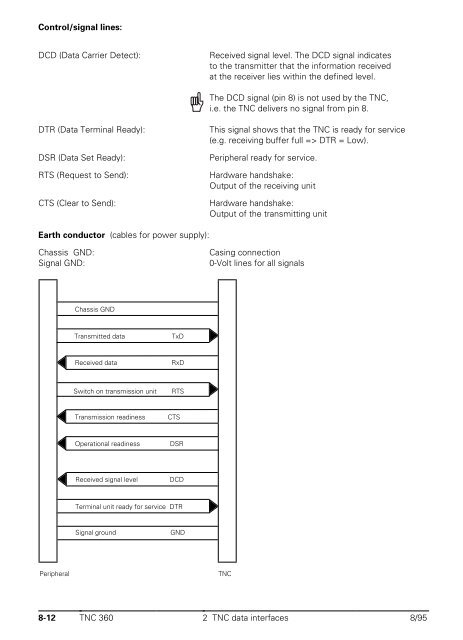
- Page 531 and 532: DTR: Polled by peripheral; it is lo
- Page 533 and 534: For the control characters for the
- Page 535 and 536: 2.6 External programming In the cas
- Page 537 and 538: 1st file 2nd file Last file Periphe
- Page 539 and 540: Peripheral unit Transmission path
- Page 541 and 542: 3.1.6 Reading in an offered program
- Page 543 and 544: 4.1.1 Calling a program directory I
- Page 545 and 546: 4.1.4 Reading in a selected program
- Page 547 and 548: 4.1.6 Reading in an offered program
- Page 549 and 550: 5 Data transfer by PLC Using PLC mo
- Page 551 and 552: 6.2 HEIDENHAIN peripherals' error c
- Page 553 and 554: OEM Cycles - Contents 1 Introductio
- Page 555 and 556: 1.1 Creating OEM cycles Programming
- Page 557 and 558: MP7240 Inhibit program input for [P
- Page 559 and 560: 2 "Bolt Hole Circle" OEM-Cycle Exam
- Page 561 and 562: 3.2 Calls in an ISO program In an I
- Page 563 and 564: 1 PLC Positioning Module 1.1 Introd
- Page 565 and 566: X25 Data interface RS-422/V.11 and
- Page 567 and 568: 1.4 Reference signal evaluation Aft
- Page 569 and 570:
Character DEC OCT HEX 0 048 060 30
- Page 571 and 572:
✎ 11-4 TNC 360 7-Bit ASCII Code8/
- Page 573 and 574:
C Call Module (CM).................
- Page 575 and 576:
Feed rate for traversing the refere
- Page 577 and 578:
Mechanical vibration...............
- Page 579 and 580:
positioning error..................
- Page 581:
Tapping with floating tap holder ..