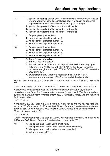
- Page 1 and 2:
OmiCheck Operating Instructions www
- Page 3 and 4:
Contents Introduction Overview.....
- Page 5 and 6:
Contents Appendix D: Manual Service
- Page 7 and 8:
Introduction Kit Contents The OmiCh
- Page 9 and 10:
Introduction Connection 1 OM1568 2
- Page 11 and 12:
Introduction Safety Precautions The
- Page 13 and 14:
Introduction Troubleshooting Proble
- Page 15 and 16:
Introduction Specification OmiCheck
- Page 17 and 18:
EOBD Identifying Compliant Vehicles
- Page 19 and 20:
EOBD Interpreting EOBD Fault Codes
- Page 21 and 22:
EOBD 1. EOBD OPERATIONS MIL Status
- Page 23 and 24:
EOBD O2 Sensor Tests EOBD has an op
- Page 25 and 26:
EOBD Main Menu Availability Manufac
- Page 27 and 28:
FastCheck Safety Instructions WARNI
- Page 29 and 30:
FastCheck ABS (Anti-lock Braking Sy
- Page 31 and 32:
FastCheck Clear DTCs Diagnostic tro
- Page 33 and 34:
FastCheck Read DTCs If any DTC code
- Page 35 and 36:
FastCheck The Disarm Passenger (LOC
- Page 37 and 38:
FastCheck Read DTCs If any DTC code
- Page 39 and 40:
FastCheck Dependent upon the vehicl
- Page 41 and 42:
FastCheck The operator will be aske
- Page 43 and 44:
FastCheck Pre-Test conditions: •
- Page 45 and 46:
FastCheck Any other EPB system comp
- Page 47 and 48:
FastCheck Latching Position This pr
- Page 49 and 50:
FastCheck Renault - Handbrake There
- Page 51 and 52:
FastCheck Replace Pads Select the R
- Page 53 and 54:
FastCheck Exit Service Mode This fu
- Page 55 and 56:
FastCheck The OmiCheck will attempt
- Page 57 and 58:
FastCheck Fiesta (2008 -), Fusion/B
- Page 59 and 60: FastCheck Service Interval This opt
- Page 61 and 62: FastCheck Select Condition Based Se
- Page 63 and 64: FastCheck The estimated distance to
- Page 65 and 66: FastCheck Annual Distance: The aver
- Page 67 and 68: FastCheck Corsa D The number of mil
- Page 69 and 70: FastCheck Land Rover vehicles There
- Page 71 and 72: FastCheck NOTE: Services which have
- Page 73 and 74: FastCheck Variable Service Reset (V
- Page 75 and 76: FastCheck Citroen, Peugeot, Fiat an
- Page 77 and 78: FastCheck Renault (Type 2) With the
- Page 79 and 80: FastCheck • Drive off. The Reset
- Page 81 and 82: FastCheck OM1346 • The Warning La
- Page 83 and 84: Manufacturer Applications Audi, Sea
- Page 85 and 86: Manufacturer Applications Adding tr
- Page 87 and 88: Manufacturer Applications Engine Co
- Page 89 and 90: Manufacturer Applications Table 1 -
- Page 91 and 92: Manufacturer Applications Table 2 -
- Page 93 and 94: Manufacturer Applications Table 3 -
- Page 95 and 96: Manufacturer Applications Table 4 -
- Page 97 and 98: Manufacturer Applications 11 1. Eng
- Page 99 and 100: Manufacturer Applications 5 1. Engi
- Page 101 and 102: Manufacturer Applications 4 1. Engi
- Page 103 and 104: Manufacturer Applications 2 1. Engi
- Page 105 and 106: Manufacturer Applications 3 1. Engi
- Page 107 and 108: Manufacturer Applications 7 1. Idli
- Page 109: Manufacturer Applications 7 1. Lamb
- Page 113 and 114: Manufacturer Applications Table 15
- Page 115 and 116: Manufacturer Applications NOTE 1: L
- Page 117 and 118: Manufacturer Applications 2 1. Engi
- Page 119 and 120: Manufacturer Applications 13 1. Ign
- Page 121 and 122: Manufacturer Applications NOTE: Tot
- Page 123 and 124: Manufacturer Applications Engine Co
- Page 125 and 126: Manufacturer Applications Engine Co
- Page 127 and 128: Manufacturer Applications Engine Co
- Page 129 and 130: Manufacturer Applications Engine Co
- Page 131 and 132: Manufacturer Applications Engine Co
- Page 133 and 134: Manufacturer Applications 5 1. Engi
- Page 135 and 136: Manufacturer Applications 15 1. Kno
- Page 137 and 138: Manufacturer Applications Table 24
- Page 139 and 140: Manufacturer Applications Table 26-
- Page 141 and 142: Manufacturer Applications Table 27-
- Page 143 and 144: Manufacturer Applications NOTE: A l
- Page 145 and 146: Manufacturer Applications 25 System
- Page 147 and 148: Manufacturer Applications 3 1. Engi
- Page 149 and 150: Manufacturer Applications 21 Lambda
- Page 151 and 152: Manufacturer Applications 3 EGR Sys
- Page 153 and 154: Manufacturer Applications Table 33
- Page 155 and 156: Manufacturer Applications 4 Injecti
- Page 157 and 158: Manufacturer Applications Table 38
- Page 159 and 160: Manufacturer Applications 2 Idling
- Page 161 and 162:
Manufacturer Applications Table 44
- Page 163 and 164:
Manufacturer Applications 7 Tempera
- Page 165 and 166:
Manufacturer Applications Table 52
- Page 167 and 168:
Manufacturer Applications NOTE: The
- Page 169 and 170:
Manufacturer Applications 54 Idling
- Page 171 and 172:
Manufacturer Applications Table 53
- Page 173 and 174:
Manufacturer Applications 3 1. Engi
- Page 175 and 176:
Manufacturer Applications 54 Idling
- Page 177 and 178:
Manufacturer Applications Table 60
- Page 179 and 180:
Manufacturer Applications 3 1. Engi
- Page 181 and 182:
Manufacturer Applications 56 Idle S
- Page 183 and 184:
Manufacturer Applications Table 71
- Page 185 and 186:
Manufacturer Applications 16 Knock
- Page 187 and 188:
Manufacturer Applications Table 76
- Page 189 and 190:
Manufacturer Applications 2 1. Engi
- Page 191 and 192:
Manufacturer Applications Table 83
- Page 193 and 194:
Manufacturer Applications Basic Set
- Page 195 and 196:
Manufacturer Applications Re-coding
- Page 197 and 198:
Manufacturer Applications Variable
- Page 199 and 200:
Manufacturer Applications BMW NOTE:
- Page 201 and 202:
Manufacturer Applications Regenerat
- Page 203 and 204:
Manufacturer Applications A fault c
- Page 205 and 206:
Manufacturer Applications 3. Wait f
- Page 207 and 208:
Manufacturer Applications Inter-cha
- Page 209 and 210:
Manufacturer Applications Bosch M7.
- Page 211 and 212:
Manufacturer Applications Magneti M
- Page 213 and 214:
Manufacturer Applications 13. Befor
- Page 215 and 216:
Manufacturer Applications Fiat, Alf
- Page 217 and 218:
Manufacturer Applications 4. The en
- Page 219 and 220:
Manufacturer Applications When the
- Page 221 and 222:
Manufacturer Applications Self Test
- Page 223 and 224:
Manufacturer Applications KO ER Tes
- Page 225 and 226:
Manufacturer Applications OM1349 OM
- Page 227 and 228:
Manufacturer Applications OM1352 1.
- Page 229 and 230:
Manufacturer Applications OM1354 2.
- Page 231 and 232:
Manufacturer Applications Live Data
- Page 233 and 234:
Manufacturer Applications A feature
- Page 235 and 236:
Manufacturer Applications Clear Fau
- Page 237 and 238:
Manufacturer Applications to re-rea
- Page 239 and 240:
Manufacturer Applications Honda ALB
- Page 241 and 242:
Manufacturer Applications Clear Fau
- Page 243 and 244:
Manufacturer Applications Transmitt
- Page 245 and 246:
Manufacturer Applications Pre-test
- Page 247 and 248:
Manufacturer Applications Pre-test
- Page 249 and 250:
Manufacturer Applications Mercedes
- Page 251 and 252:
Manufacturer Applications If the Om
- Page 253 and 254:
Manufacturer Applications 72 Pyrote
- Page 255 and 256:
Manufacturer Applications Renault E
- Page 257 and 258:
Manufacturer Applications Renault T
- Page 259 and 260:
Manufacturer Applications Renault (
- Page 261 and 262:
User Menu Tester Setup The tester s
- Page 263 and 264:
User Menu Security Most of the appl
- Page 265 and 266:
Glossary of terms Term Description
- Page 267 and 268:
262 Appendix A: Glossary ESV (Drive
- Page 269 and 270:
MPH miles per hour MST Manifold Sur
- Page 271 and 272:
TVV Thermal Vacuum Valve TWC Three
- Page 273 and 274:
CR0231 CR0230 OG2013 - PSA 30 pin c
- Page 275 and 276:
CR0228 CR0235 OG2002 - BMW cable OG
- Page 277 and 278:
Appendix C: Diagnostic Connector Lo
- Page 279 and 280:
Appendix C: Diagnostic Connector Lo
- Page 281 and 282:
Appendix C: Diagnostic Connector Lo
- Page 283 and 284:
Appendix C: Diagnostic Connector Lo
- Page 285 and 286:
Appendix C: Diagnostic Connector Lo
- Page 287 and 288:
Appendix C: Diagnostic Connector Lo
- Page 289 and 290:
Appendix C: Diagnostic Connector Lo
- Page 291 and 292:
Appendix D: Manual Service Reset Au
- Page 293 and 294:
Appendix D: Manual Service Reset NO
- Page 295 and 296:
Appendix D: Manual Service Reset C3
- Page 297 and 298:
Appendix D: Manual Service Reset Re
- Page 299 and 300:
Appendix D: Manual Service Reset Xs
- Page 301 and 302:
Appendix D: Manual Service Reset Fi
- Page 303 and 304:
Appendix D: Manual Service Reset GM
- Page 305 and 306:
Appendix D: Manual Service Reset La
- Page 307 and 308:
Appendix D: Manual Service Reset Pe
- Page 309 and 310:
Appendix D: Manual Service Reset 40
- Page 311 and 312:
Appendix D: Manual Service Reset Bo
- Page 313 and 314:
Appendix D: Manual Service Reset Re
- Page 315 and 316:
Appendix D: Manual Service Reset La
- Page 317 and 318:
Appendix D: Manual Service Reset Ve
- Page 319 and 320:
Appendix D: Manual Service Reset Vo
- Page 321 and 322:
Appendix D: Manual Service Reset Vo
- Page 323 and 324:
Appendix D: Manual Service Reset Vo
- Page 325:
Omitec Hopton Industrial Estate Lon


