
Create successful ePaper yourself
Turn your PDF publications into a flip-book with our unique Google optimized e-Paper software.
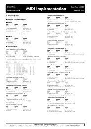
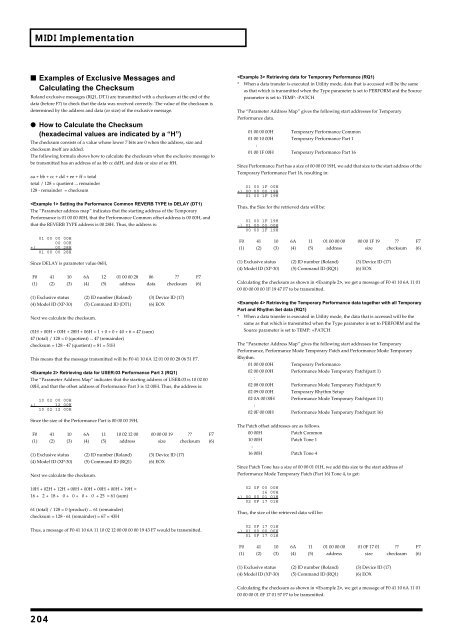
MIDI Implementation<br />
■ Examples of Exclusive Messages and<br />
Calculating the Checksum<br />
<strong>Roland</strong> exclusive messages (RQ1, DT1) are transmitted with a checksum at the end of the<br />
data (before F7) to check that the data was received correctly. The value of the checksum is<br />
determined by the address and data (or size) of the exclusive message.<br />
● How to Calculate the Checksum<br />
(hexadecimal values are indicated by a “H”)<br />
The checksum consists of a value whose lower 7 bits are 0 when the address, size and<br />
checksum itself are added.<br />
The following formula shows how to calculate the checksum when the exclusive message to<br />
be transmitted has an address of aa bb cc ddH, and data or size of ee ffH.<br />
aa + bb + cc + dd + ee + ff = total<br />
total / 128 = quotient ... remainder<br />
128 - remainder = checksum<br />
Setting the Performance Common REVERB TYPE to DELAY (DT1)<br />
The “Parameter address map” indicates that the starting address of the Temporary<br />
Performance is 01 00 00 00H, that the Performance Common offset address is 00 00H, and<br />
that the REVERB TYPE address is 00 28H. Thus, the address is:<br />
01 00 00 00H<br />
00 00H<br />
+) 00 28H<br />
01 00 00 28H<br />
Since DELAY is parameter value 06H,<br />
F0 41 10 6A 12 01 00 00 28 06 ?? F7<br />
(1) (2) (3) (4) (5) address data checksum (6)<br />
(1) Exclusive status (2) ID number (<strong>Roland</strong>) (3) Device ID (17)<br />
(4) Model ID (XP-30) (5) Command ID (DT1) (6) EOX<br />
Next we calculate the checksum.<br />
01H + 00H + 00H + 28H + 06H = 1 + 0 + 0 + 40 + 6 = 47 (sum)<br />
47 (total) / 128 = 0 (quotient) ... 47 (remainder)<br />
checksum = 128 - 47 (quotient) = 81 = 51H<br />
This means that the message transmitted will be F0 41 10 6A 12 01 00 00 28 06 51 F7.<br />
Retrieving data for USER:03 Performance Part 3 (RQ1)<br />
The “Parameter Address Map” indicates that the starting address of USER:03 is 10 02 00<br />
00H, and that the offset address of Performance Part 3 is 12 00H. Thus, the address is:<br />
10 02 00 00H<br />
+) 12 00H<br />
10 02 12 00H<br />
Since the size of the Performance Part is 00 00 00 19H,<br />
F0 41 10 6A 11 10 02 12 00 00 00 00 19 ?? F7<br />
(1) (2) (3) (4) (5) address size checksum (6)<br />
(1) Exclusive status (2) ID number (<strong>Roland</strong>) (3) Device ID (17)<br />
(4) Model ID (XP-30) (5) Command ID (RQ1) (6) EOX<br />
Next we calculate the checksum.<br />
10H + 02H + 12H + 00H + 00H + 00H + 00H + 19H =<br />
16 + 2 + 18 + 0 + 0 + 0 + 0 + 25 = 61 (sum)<br />
61 (total) / 128 = 0 (product) ... 61 (remainder)<br />
checksum = 128 - 61 (remainder) = 67 = 43H<br />
Thus, a message of F0 41 10 6A 11 10 02 12 00 00 00 00 19 43 F7 would be transmitted.<br />
Retrieving data for Temporary Performance (RQ1)<br />
* When a data transfer is executed in Utility mode, data that is accessed will be the same<br />
as that which is transmitted when the Type parameter is set to PERFORM and the Source<br />
parameter is set to TEMP: -PATCH<br />
The “Parameter Address Map” gives the following start addresses for Temporary<br />
Performance data.<br />
01 00 00 00H Temporary Performance Common<br />
01 00 10 00H Temporary Performance Part 1<br />
:<br />
01 00 1F 00H Temporary Performance Part 16<br />
Since Performance Part has a size of 00 00 00 19H, we add that size to the start address of the<br />
Temporary Performance Part 16, resulting in:<br />
01 00 1F 00H<br />
+) 00 00 00 19H<br />
01 00 1F 19H<br />
Thus, the Size for the retrieved data will be:<br />
01 00 1F 19H<br />
-) 01 00 00 00H<br />
00 00 1F 19H<br />
F0 41 10 6A 11 01 00 00 00 00 00 1F 19 ?? F7<br />
(1) (2) (3) (4) (5) address size checksum (6)<br />
(1) Exclusive status (2) ID number (<strong>Roland</strong>) (3) Device ID (17)<br />
(4) Model ID (XP-30) (5) Command ID (RQ1) (6) EOX<br />
Calculating the checksum as shown in , we get a message of F0 41 10 6A 11 01<br />
00 00 00 00 00 1F 19 47 F7 to be transmitted.<br />
Retrieving the Temporary Performance data together with all Temporary<br />
Part and Rhythm Set data (RQ1)<br />
* When a data transfer is executed in Utility mode, the data that is accessed will be the<br />
same as that which is transmitted when the Type parameter is set to PERFORM and the<br />
Source parameter is set to TEMP: +PATCH<br />
The “Parameter Address Map” gives the following start addresses for Temporary<br />
Performance, Performance Mode Temporary Patch and Performance Mode Temporary<br />
Rhythm.<br />
01 00 00 00H Temporary Performance<br />
02 00 00 00H Performance Mode Temporary Patch(part 1)<br />
:<br />
02 08 00 00H Performance Mode Temporary Patch(part 9)<br />
02 09 00 00H Temporary Rhythm Setup<br />
02 0A 00 00H Performance Mode Temporary Patch(part 11)<br />
:<br />
02 0F 00 00H Performance Mode Temporary Patch(part 16)<br />
The Patch offset addresses are as follows.<br />
00 00H Patch Common<br />
10 00H Patch Tone 1<br />
:<br />
16 00H Patch Tone 4<br />
Since Patch Tone has a size of 00 00 01 01H, we add this size to the start address of<br />
Performance Mode Temporary Patch (Part 16) Tone 4, to get:<br />
02 0F 00 00H<br />
16 00H<br />
+) 00 00 01 01H<br />
02 0F 17 01H<br />
Thus, the size of the retrieved data will be:<br />
02 0F 17 01H<br />
-) 01 00 00 00H<br />
01 0F 17 01H<br />
F0 41 10 6A 11 01 00 00 00 01 0F 17 01 ?? F7<br />
(1) (2) (3) (4) (5) address size checksum (6)<br />
(1) Exclusive status (2) ID number (<strong>Roland</strong>) (3) Device ID (17)<br />
(4) Model ID (XP-30) (5) Command ID (RQ1) (6) EOX<br />
Calculating the checksum as shown in , we get a message of F0 41 10 6A 11 01<br />
00 00 00 01 0F 17 01 57 F7 to be transmitted.<br />
204