

PXA3xx Design Guide - Marvell
PXA3xx Design Guide - Marvell
PXA3xx Design Guide - Marvell
- No tags were found...

You also want an ePaper? Increase the reach of your titles
YUMPU automatically turns print PDFs into web optimized ePapers that Google loves.
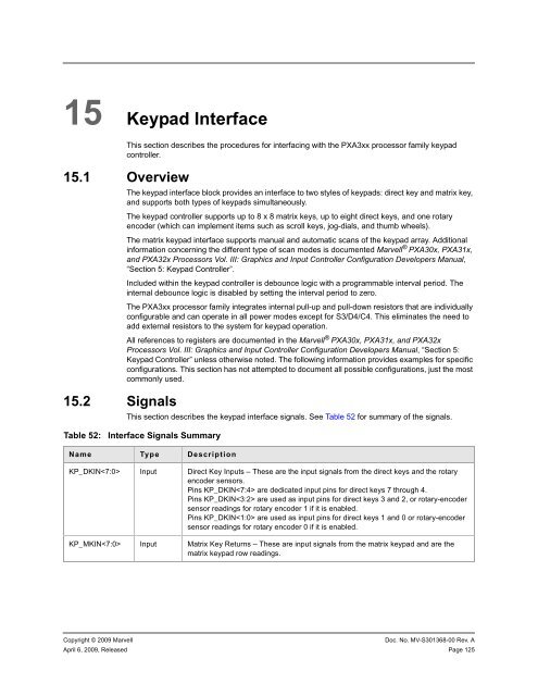
15 Keypad InterfaceThis section describes the procedures for interfacing with the <strong>PXA3xx</strong> processor family keypadcontroller.15.1 Overview15.2 SignalsThe keypad interface block provides an interface to two styles of keypads: direct key and matrix key,and supports both types of keypads simultaneously.The keypad controller supports up to 8 x 8 matrix keys, up to eight direct keys, and one rotaryencoder (which can implement items such as scroll keys, jog-dials, and thumb wheels).The matrix keypad interface supports manual and automatic scans of the keypad array. Additionalinformation concerning the different type of scan modes is documented <strong>Marvell</strong> ® PXA30x, PXA31x,and PXA32x Processors Vol. III: Graphics and Input Controller Configuration Developers Manual,“Section 5: Keypad Controller”.Included within the keypad controller is debounce logic with a programmable interval period. Theinternal debounce logic is disabled by setting the interval period to zero.The <strong>PXA3xx</strong> processor family integrates internal pull-up and pull-down resistors that are individuallyconfigurable and can operate in all power modes except for S3/D4/C4. This eliminates the need toadd external resistors to the system for keypad operation.All references to registers are documented in the <strong>Marvell</strong> ® PXA30x, PXA31x, and PXA32xProcessors Vol. III: Graphics and Input Controller Configuration Developers Manual, “Section 5:Keypad Controller” unless otherwise noted. The following information provides examples for specificconfigurations. This section has not attempted to document all possible configurations, just the mostcommonly used.This section describes the keypad interface signals. See Table 52 for summary of the signals.Table 52:Interface Signals SummaryName Type DescriptionKP_DKIN Input Direct Key Inputs – These are the input signals from the direct keys and the rotaryencoder sensors.Pins KP_DKIN are dedicated input pins for direct keys 7 through 4.Pins KP_DKIN are used as input pins for direct keys 3 and 2, or rotary-encodersensor readings for rotary encoder 1 if it is enabled.Pins KP_DKIN are used as input pins for direct keys 1 and 0 or rotary-encodersensor readings for rotary encoder 0 if it is enabled.KP_MKIN Input Matrix Key Returns – These are input signals from the matrix keypad and are thematrix keypad row readings.Copyright © 2009 <strong>Marvell</strong>Doc. No. MV-S301368-00 Rev. AApril 6, 2009, Released Page 125


