PXA3xx Design Guide - Marvell
PXA3xx Design Guide - Marvell
PXA3xx Design Guide - Marvell
- No tags were found...
You also want an ePaper? Increase the reach of your titles
YUMPU automatically turns print PDFs into web optimized ePapers that Google loves.
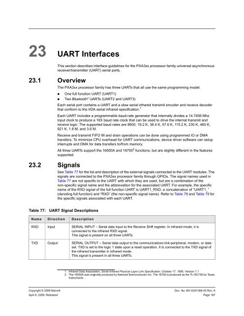
23 UART InterfacesThis section describes interface guidelines for the <strong>PXA3xx</strong> processor family universal asynchronousreceiver/transmitter (UART) serial ports.23.1 Overview23.2 SignalsThe <strong>PXA3xx</strong> processor family has three UARTs that all use the same programming model:• One full function UART (UART1)• Two Bluetooth* UARTs (UART2 and UART3)Each serial port contains a UART and a slow serial infrared transmit encoder and receive decoderthat conform to the IrDA serial infrared specification. 1Each UART includes a programmable baud-rate generator that internally divides a 14.7456 Mhzinput clock to produce a 16X baud rate clock that can be used to drive the internal transmit andreceive logic. The supported baud rates are 9600, 19.2 K, 38.4 K, 57.6 K, 115.2 K, 230 K, 460 K,921 K, 1.8 M, and 3.6 M.Receive and transmit FIFO fill and drain operations can be done using programmed IO or DMAtransfers. To minimize CPU overhead for UART communications, device driver software can setupinterrupts and DMA for data transfers to/from memory.All three UARTs support the 16550A and 16750 2 functions, but are slightly different in the featuressupported.See Table 77 for the list and description of the external signals connected to the UART modules. Thesignals are connected to the <strong>PXA3xx</strong> processor family through GPIOs. The signal names used inTable 77 are not specific to the UART with which they are used, but are a combination of thenon-specific signal name and the abbreviation for the associated UART. For example, the specificname of the RXD signal of the full function UART is UART1_RXD, a concatenation of “UART1_”(denoting full function) and “RXD” (the non-specific signal name). Refer to Table 78 and Table 79 forthe specific signals associated with each UART.Table 77:UART Signal DescriptionsName Direction DescriptionRXD Input SERIAL INPUT – Serial data input to the Receive Shift register. In infrared mode, it isconnected to the infrared RXD signal.This signal is present on all three UARTs.TXD Output SERIAL OUTPUT – Serial data output to the communications link-peripheral, modem, or dataset. TXD is set to the logic 1 state upon a reset operation. It is connected to the TXD signal ofthe infrared transmitter in infrared mode.This signal is present in all three UARTs.1. Infrared Data Association, Serial Infrared Physical Layer Link Specification, October 17, 1995, Version 1.12. The 16550A was originally produced by National Semiconductor Inc. The 16750 is produced as the TL16C750 by TexasInstruments.Copyright © 2009 <strong>Marvell</strong>Doc. No. MV-S301368-00 Rev. AApril 6, 2009, Released Page 187


