PXA3xx Design Guide - Marvell
PXA3xx Design Guide - Marvell
PXA3xx Design Guide - Marvell
- No tags were found...
You also want an ePaper? Increase the reach of your titles
YUMPU automatically turns print PDFs into web optimized ePapers that Google loves.
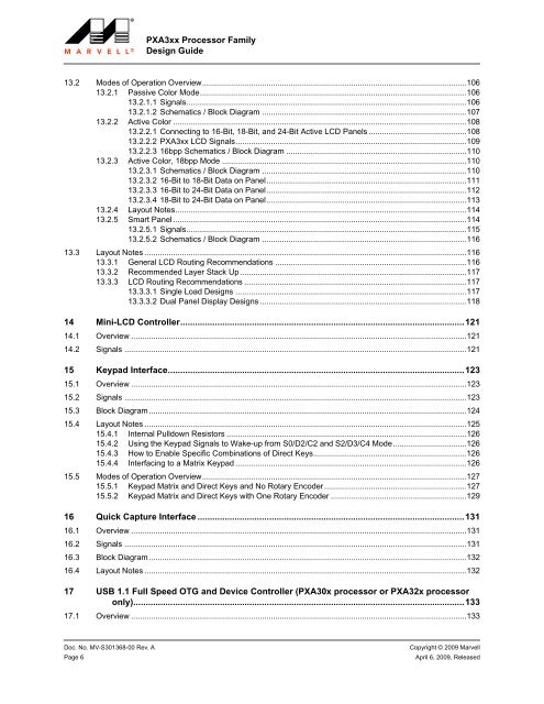
<strong>PXA3xx</strong> Processor Family<strong>Design</strong> <strong>Guide</strong>13.2 Modes of Operation Overview.......................................................................................................................10613.2.1 Passive Color Mode........................................................................................................................10613.2.1.1 Signals..............................................................................................................................10613.2.1.2 Schematics / Block Diagram ............................................................................................10713.2.2 Active Color ....................................................................................................................................10813.2.2.1 Connecting to 16-Bit, 18-Bit, and 24-Bit Active LCD Panels ............................................10813.2.2.2 <strong>PXA3xx</strong> LCD Signals........................................................................................................10913.2.2.3 16bpp Schematics / Block Diagram .................................................................................11013.2.3 Active Color, 18bpp Mode ..............................................................................................................11013.2.3.1 Schematics / Block Diagram ............................................................................................11013.2.3.2 16-Bit to 18-Bit Data on Panel..........................................................................................11113.2.3.3 16-Bit to 24-Bit Data on Panel..........................................................................................11213.2.3.4 18-Bit to 24-Bit Data on Panel..........................................................................................11313.2.4 Layout Notes...................................................................................................................................11413.2.5 Smart Panel ....................................................................................................................................11413.2.5.1 Signals..............................................................................................................................11513.2.5.2 Schematics / Block Diagram ............................................................................................11613.3 Layout Notes .................................................................................................................................................11613.3.1 General LCD Routing Recommendations ......................................................................................11613.3.2 Recommended Layer Stack Up......................................................................................................11713.3.3 LCD Routing Recommendations ....................................................................................................11713.3.3.1 Single Load <strong>Design</strong>s ........................................................................................................11713.3.3.2 Dual Panel Display <strong>Design</strong>s .............................................................................................11814 Mini-LCD Controller...................................................................................................................12114.1 Overview .......................................................................................................................................................12114.2 Signals ..........................................................................................................................................................12115 Keypad Interface........................................................................................................................12315.1 Overview .......................................................................................................................................................12315.2 Signals ..........................................................................................................................................................12315.3 Block Diagram...............................................................................................................................................12415.4 Layout Notes .................................................................................................................................................12515.4.1 Internal Pulldown Resistors ............................................................................................................12615.4.2 Using the Keypad Signals to Wake-up from S0/D2/C2 and S2/D3/C4 Mode.................................12615.4.3 How to Enable Specific Combinations of Direct Keys.....................................................................12615.4.4 Interfacing to a Matrix Keypad ........................................................................................................12615.5 Modes of Operation Overview.......................................................................................................................12715.5.1 Keypad Matrix and Direct Keys and No Rotary Encoder................................................................12715.5.2 Keypad Matrix and Direct Keys with One Rotary Encoder .............................................................12916 Quick Capture Interface ............................................................................................................13116.1 Overview .......................................................................................................................................................13116.2 Signals ..........................................................................................................................................................13116.3 Block Diagram...............................................................................................................................................13216.4 Layout Notes .................................................................................................................................................13217 USB 1.1 Full Speed OTG and Device Controller (PXA30x processor or PXA32x processoronly)......................................................................................................................................13317.1 Overview .......................................................................................................................................................133Doc. No. MV-S301368-00 Rev. A Copyright © 2009 <strong>Marvell</strong>Page 6April 6, 2009, Released


