PXA3xx Design Guide - Marvell
PXA3xx Design Guide - Marvell
PXA3xx Design Guide - Marvell
- No tags were found...
Create successful ePaper yourself
Turn your PDF publications into a flip-book with our unique Google optimized e-Paper software.
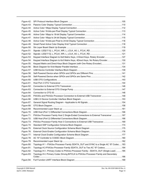
Figure 42: SPI Protocol Interface Block Diagram ............................................................................................105Figure 43: Passive Color Display Typical Connection .....................................................................................110Figure 44: Active Color 16bpp Display Typical Connection .............................................................................112Figure 45: Active Color 18-bits-per-Pixel Display Typical Connection.............................................................113Figure 46: Active Color 16bpp to 18-bit Display Typical Connection ...............................................................114Figure 47: Active Color 16bpp to 24-bit Display Typical Connection ...............................................................115Figure 48: Active Color 18-bits-per-Pixel to 24-bit Display Typical Connection...............................................116Figure 49: Smart Panel Active Color Display 8-bit Typical Connection ...........................................................118Figure 50: SIx Layer Board Stack Up Example ...............................................................................................119Figure 51: Signals: LDD[17:0], L_PCLK_WR, L_LCLK_A0, L_FCLK_RD.......................................................120Figure 52: Signals: LDD[17:0], L_PCLK_WR, L_LCLK_A0, L_FCLK_RD.......................................................121Figure 53: Keypad Interface Diagram to 8x8 Matrix Keys, 4 Direct Keys, Rotary Encoder .............................127Figure 54: Keypad Interface Diagram to 6x3 Matrix Keys, 4Direct Keys, No Rotary Encoder.........................130Figure 55: Keypad Matrix and Direct Keys Block Diagram (with One Rotary Encoder)...................................131Figure 56: Block Diagram for 8-bit Master Parallel Interface ...........................................................................134Figure 57: USB Device Controller Interface Block Diagram.............................................................................139Figure 58: Self-Powered Device when GPIOn and GPIOx are Different Pins .................................................141Figure 59: Self-Powered Device when GPIOn and GPIOx are Same Pins .....................................................142Figure 60: USB OTG Configurations ...............................................................................................................143Figure 61: Host Port 2 OTG Transceiver .........................................................................................................144Figure 62: Connection to External OTG Transceiver.......................................................................................146Figure 63: Connection to External OTG Charge Pump ...................................................................................147Figure 64: Connection to OTG ID ....................................................................................................................148Figure 65: PXA30x and PXA32x Processor Connection to External USB Transceiver ...................................148Figure 66: USB 2.0 Device Controller Interface Block Diagram.......................................................................153Figure 67: General Signal Routing Diagram - Applicable to All Signals...........................................................154Figure 68: OTG Block Diagram........................................................................................................................158Figure 69: Recommended Layer Stack up ......................................................................................................161Figure 70: USB Host (Port 1) Differential Connections Block Diagram............................................................166Figure 71: <strong>PXA3xx</strong> Processor Family Host 2 Single-Ended Connections to External Transceiver .................167Figure 72: USB Host (Port 2) Differential Connections Block Diagram............................................................168Figure 73: <strong>PXA3xx</strong> Processor Family Host 3 Connections to External USB Transceiver................................169Figure 74: Standard SSP Configuration Schema Block Diagram ....................................................................174Figure 75: External Clock Source Configuration Schema Block Diagram .......................................................175Figure 76: External Clock Enable Configuration Schema Block Diagram........................................................176Figure 77: Internal Clock Enable Configuration Scheme Block Diagram.........................................................177Figure 78: AC ‘97 Controller to CODEC Block Diagram ..................................................................................180Figure 79: Recommended Layer Stack Up......................................................................................................182Figure 80: Topology # 1 - <strong>PXA3xx</strong> Processor Family SDATA_OUT and SYNC to a Single AC ‘97 Codec.....183Figure 81: Topology # 2-<strong>PXA3xx</strong> Processor Family SDATA_OUT to Two AC ‘97 Codecs.............................184Figure 82: Topology # 3 - Primary Codec to <strong>PXA3xx</strong> Processor Family - SDATA_OUT (Single Load) ..........185Figure 83: Topology # 4: Primary Codec Driving BITCLK to <strong>PXA3xx</strong> Processor Family and SecondaryCodec .............................................................................................................................................186Figure 84: Full Function UART Interface Block Diagram .................................................................................189Copyright © 2009 <strong>Marvell</strong>Doc. No. MV-S301368-00 Rev. AApril 6, 2009, Released Page 13


