PXA3xx Design Guide - Marvell
PXA3xx Design Guide - Marvell
PXA3xx Design Guide - Marvell
- No tags were found...
You also want an ePaper? Increase the reach of your titles
YUMPU automatically turns print PDFs into web optimized ePapers that Google loves.
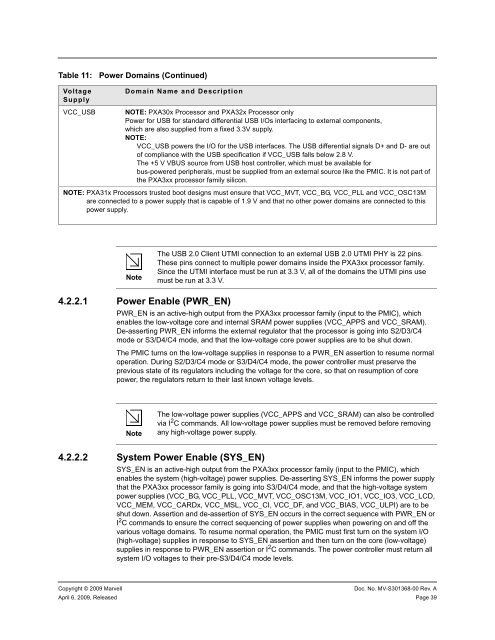
Table 11:VoltageSupplyVCC_USBPower Domains (Continued)Domain Name and DescriptionNOTE: PXA30x Processor and PXA32x Processor onlyPower for USB for standard differential USB I/Os interfacing to external components,which are also supplied from a fixed 3.3V supply.NOTE:VCC_USB powers the I/O for the USB interfaces. The USB differential signals D+ and D- are outof compliance with the USB specification if VCC_USB falls below 2.8 V.The +5 V VBUS source from USB host controller, which must be available forbus-powered peripherals, must be supplied from an external source like the PMIC. It is not part ofthe <strong>PXA3xx</strong> processor family silicon.NOTE: PXA31x Processors trusted boot designs must ensure that VCC_MVT, VCC_BG, VCC_PLL and VCC_OSC13Mare connected to a power supply that is capable of 1.9 V and that no other power domains are connected to thispower supply.NoteThe USB 2.0 Client UTMI connection to an external USB 2.0 UTMI PHY is 22 pins.These pins connect to multiple power domains inside the <strong>PXA3xx</strong> processor family.Since the UTMI interface must be run at 3.3 V, all of the domains the UTMI pins usemust be run at 3.3 V.4.2.2.1 Power Enable (PWR_EN)PWR_EN is an active-high output from the <strong>PXA3xx</strong> processor family (input to the PMIC), whichenables the low-voltage core and internal SRAM power supplies (VCC_APPS and VCC_SRAM).De-asserting PWR_EN informs the external regulator that the processor is going into S2/D3/C4mode or S3/D4/C4 mode, and that the low-voltage core power supplies are to be shut down.The PMIC turns on the low-voltage supplies in response to a PWR_EN assertion to resume normaloperation. During S2/D3/C4 mode or S3/D4/C4 mode, the power controller must preserve theprevious state of its regulators including the voltage for the core, so that on resumption of corepower, the regulators return to their last known voltage levels.NoteThe low-voltage power supplies (VCC_APPS and VCC_SRAM) can also be controlledvia I 2 C commands. All low-voltage power supplies must be removed before removingany high-voltage power supply.4.2.2.2 System Power Enable (SYS_EN)SYS_EN is an active-high output from the <strong>PXA3xx</strong> processor family (input to the PMIC), whichenables the system (high-voltage) power supplies. De-asserting SYS_EN informs the power supplythat the <strong>PXA3xx</strong> processor family is going into S3/D4/C4 mode, and that the high-voltage systempower supplies (VCC_BG, VCC_PLL, VCC_MVT, VCC_OSC13M, VCC_IO1, VCC_IO3, VCC_LCD,VCC_MEM, VCC_CARDx, VCC_MSL, VCC_CI, VCC_DF, and VCC_BIAS, VCC_ULPI) are to beshut down. Assertion and de-assertion of SYS_EN occurs in the correct sequence with PWR_EN orI 2 C commands to ensure the correct sequencing of power supplies when powering on and off thevarious voltage domains. To resume normal operation, the PMIC must first turn on the system I/O(high-voltage) supplies in response to SYS_EN assertion and then turn on the core (low-voltage)supplies in response to PWR_EN assertion or I 2 C commands. The power controller must return allsystem I/O voltages to their pre-S3/D4/C4 mode levels.Copyright © 2009 <strong>Marvell</strong>Doc. No. MV-S301368-00 Rev. AApril 6, 2009, Released Page 39


