Download - Freiwald Software
Download - Freiwald Software
Download - Freiwald Software

You also want an ePaper? Increase the reach of your titles
YUMPU automatically turns print PDFs into web optimized ePapers that Google loves.
Diagram 91 shows a block driven by one occupancy (B) and two momentary sensors (A<br />
and C). Each of these sensors is associated with a contact indicator in the software<br />
called A, B and C. All indicators are assigned to the same block in the software. The<br />
block is indicated as occupied as soon as a train enters section B from any direction.<br />
The block remains occupied until the train leaves section B. The indicator A is additionally<br />
used as stop indicator for trains running to the left, C acts as stop indicator for<br />
trains running to the right. Both indicators additionally act as brake indicators for the<br />
opposite direction, respectively. The location of A and C should ensure, that each train<br />
is safely stopped before touching one of the switches. On the other side the longest train<br />
should completely fit into the block when being stopped. For this reason A or C, respectively,<br />
where trains are stopped, must be located close enough to the boundaries of the<br />
complete block.<br />
The configuration displayed in Diagram 91 is usually less expensive then that displayed<br />
in Diagram 90, because momentary contacts are usually less expensive then occupancy<br />
sensors.<br />
122<br />
A C<br />
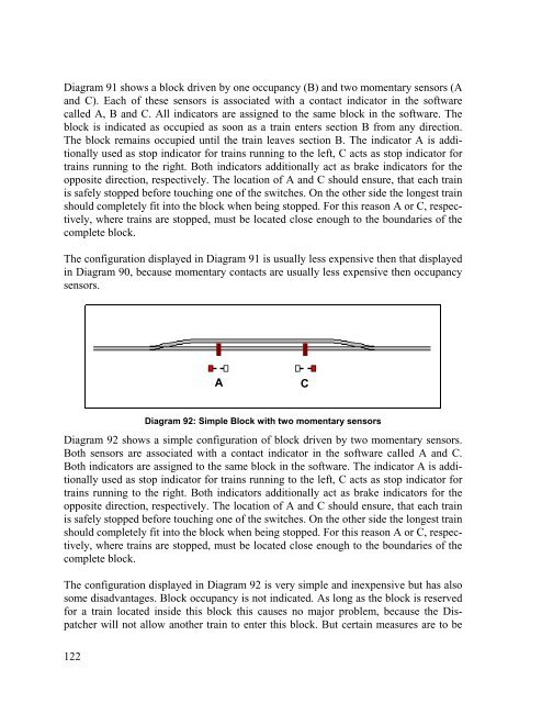
Diagram 92: Simple Block with two momentary sensors<br />
Diagram 92 shows a simple configuration of block driven by two momentary sensors.<br />
Both sensors are associated with a contact indicator in the software called A and C.<br />
Both indicators are assigned to the same block in the software. The indicator A is additionally<br />
used as stop indicator for trains running to the left, C acts as stop indicator for<br />
trains running to the right. Both indicators additionally act as brake indicators for the<br />
opposite direction, respectively. The location of A and C should ensure, that each train<br />
is safely stopped before touching one of the switches. On the other side the longest train<br />
should completely fit into the block when being stopped. For this reason A or C, respectively,<br />
where trains are stopped, must be located close enough to the boundaries of the<br />
complete block.<br />
The configuration displayed in Diagram 92 is very simple and inexpensive but has also<br />
some disadvantages. Block occupancy is not indicated. As long as the block is reserved<br />
for a train located inside this block this causes no major problem, because the Dispatcher<br />
will not allow another train to enter this block. But certain measures are to be