- Page 1 and 2:
RAILROAD & CO. ® TrainController
- Page 3 and 4:
Table of Contents About this Docume
- Page 5 and 6:
Momentary Track Contacts vs. Occupa
- Page 7 and 8:
Example: Detecting uncoupled Cars..
- Page 9 and 10:
About this Document RAILROAD & CO.
- Page 11 and 12:
Part I Quick Start B 11
- Page 13 and 14:
Diagram 1: TrainController Setup Sc
- Page 15 and 16:
In order to test, whether the conne
- Page 17 and 18:
Diagram 5: Train Window If you want
- Page 19 and 20:
Controlling a Train Diagram 8: Trai
- Page 21 and 22:
Diagram 10: Tools Menu Now move the
- Page 23 and 24:
the switches are correctly working
- Page 25 and 26:
Quick Start - Step 4: Creating Bloc
- Page 27 and 28:
Diagram 18: Tools Menu Now click to
- Page 29 and 30:
Diagram 22: Assigning a Contact Ind
- Page 31 and 32:
Diagram 25: Block Menu In the follo
- Page 33 and 34:
Quick Start - Step 5: Controlling T
- Page 35 and 36:
“Block 4”. Then select “Block
- Page 37:
Diagram 33: Specifying a Wait Time
- Page 40 and 41:
B 40 1 Introduction 1.1 Overview Tr
- Page 42 and 43:
This feature is useful if, • you
- Page 44 and 45:
44 Diagram 34: RAILROAD & CO. Train
- Page 46 and 47:
You can also decide to do without t
- Page 48 and 49:
Users, who are familiar with HTML a
- Page 50 and 51:
50 Train Windows The train window e
- Page 52 and 53:
B 52 2 The Switchboard 2.1 Introduc
- Page 54 and 55:
B The following steps are performed
- Page 56 and 57:
56 Diagram 39 Diagram 40 Diagram 41
- Page 58 and 59:
! controlling the specified switch.
- Page 60 and 61:
The bright circles represent the co
- Page 62 and 63:
B Push buttons and on-off switches
- Page 64 and 65:
• Stop with Save: Recording is te
- Page 66 and 67:
66 Interlinking Routes The path of
- Page 68 and 69:
If there is a known engine or train
- Page 70 and 71:
! process several image formats, am
- Page 72 and 73:
For each engine you can specify its
- Page 74 and 75: B 74 3.4 Speedometer and Odometer T
- Page 76 and 77: ! X 76 Diagram 59: Adjusting the si
- Page 78 and 79: ! Before an automatic measurement o
- Page 80 and 81: ! Please ensure, that the indicator
- Page 82 and 83: esponding engine decoder is assigne
- Page 84 and 85: 84 3.7 Multiple Units TrainControll
- Page 86 and 87: 86 Example: Automatic Car Lighting
- Page 88 and 89: with the inertia as desired. The ad
- Page 90 and 91: ! The assignment of control is perf
- Page 92 and 93: sensors. More details about running
- Page 94 and 95: 94 Contact Indicator Diagram 71: Tr
- Page 96 and 97: B 96 5 The Visual Dispatcher I 5.1
- Page 98 and 99: 98 Diagram 75: Sample Layout The la
- Page 100 and 101: B 100 Diagram 77: Switchboard of th
- Page 102 and 103: Each blue track section represents
- Page 104 and 105: ! 104 Diagram 80: Main Block Diagra
- Page 106 and 107: B is possible to zoom and scroll th
- Page 108 and 109: 108 Occupied Block A block is assum
- Page 110 and 111: 110 Display of Train Positions The
- Page 112 and 113: Finally the train IDs are entered i
- Page 114 and 115: B ! 114 Train Tracking The Visual D
- Page 116 and 117: In order to create a block all indi
- Page 118 and 119: 118 Normal Speed Threshold Speed St
- Page 120 and 121: ! ! B B TrainController assumes tha
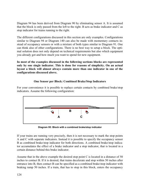
- Page 122 and 123: Diagram 91 shows a block driven by
- Page 126 and 127: “The engineer is able to see the
- Page 128 and 129: 128 Diagram 97: Integrated Block Si
- Page 130 and 131: B 130 5.10 Schedules Schedule Diagr
- Page 132 and 133: 132 Diagram 100: Schedule Specific
- Page 134 and 135: • If end blocks shall be used as
- Page 136 and 137: are used as starting blocks and the
- Page 138 and 139: B ! B 138 Starting a Schedule Each
- Page 140 and 141: ! In the diagram displayed above th
- Page 142 and 143: B B 142 Release of Blocks and Route
- Page 144 and 145: ! In the example displayed above ea
- Page 146 and 147: B way you can operate your favorite
- Page 148 and 149: X blocks or routes, that are curren
- Page 150 and 151: B 150 6 The Traffic Control During
- Page 152 and 153: 152 Diagram 108: Inspector
- Page 154 and 155: ! It is also possible, to copy the
- Page 156 and 157: ! 156 Northville Hidden Yard Southt
- Page 158 and 159: 158 Diagram 112: Engine list By edi
- Page 160 and 161: 160 Diagram 114: Switchboard with T
- Page 162 and 163: 162 Main Line West Northville Hidde
- Page 164 and 165: The indicator “Southtown East Ent
- Page 167 and 168: Part III Extensions X 167
- Page 169 and 170: 10 The Object Explorer The Object E
- Page 171 and 172: ! Even though a link to the object
- Page 173 and 174: 11 The Clock TrainController can di
- Page 175 and 176:
Diagram 120: Memory of a an Indicat
- Page 177 and 178:
Diagram 121: Conditions of a signal
- Page 179 and 180:
Diagram 122: Operations of a push b
- Page 181 and 182:
X Hot Key Operations Push Button
- Page 183 and 184:
Flagmen and Conditions It is also p
- Page 185 and 186:
Diagram 125: Detecting uncoupled Ca
- Page 187 and 188:
X This mechanism also works if the
- Page 189 and 190:
This is done in the following way:
- Page 191 and 192:
X 13 The Visual Dispatcher II 13.1
- Page 193 and 194:
Diagram 128: Main Block Diagram in
- Page 195 and 196:
! ! is possible to zoom and scroll
- Page 197 and 198:
Diagram 133: Multiple Routes withou
- Page 199 and 200:
Diagram 135: Arranging a Virtual Co
- Page 201 and 202:
does not need a very exact location
- Page 203 and 204:
! X and A is large enough. Even tho
- Page 205 and 206:
X cuted. Such local per-schedule co
- Page 207 and 208:
X A typical example of a critical s
- Page 209 and 210:
! on this switch you can intervene
- Page 211 and 212:
Example: Manual Control of Station
- Page 213 and 214:
• Trains enter the hidden yard th
- Page 215 and 216:
This schedule can be linked to sche
- Page 217 and 218:
Diagram 152: Timetable in the Dispa
- Page 219 and 220:
Special features are: Diagram 154:
- Page 221 and 222:
! 14.3 The Type of a Turntable/Tran
- Page 223 and 224:
! tails about digital addresses and
- Page 225 and 226:
! Diagram 158: Assigning feedback i
- Page 227 and 228:
Using different routes and schedule
- Page 229 and 230:
Diagram 162: Move with Turn to the
- Page 231 and 232:
! Diagram 163: Turn Boundary The bl
- Page 233 and 234:
Route Operation Entry to Bridge Tur
- Page 235 and 236:
Diagram 166: Schedule for automatic
- Page 237 and 238:
Diagram 168: During the turn 237
- Page 239 and 240:
Diagram 170: Engine is moving backw
- Page 241 and 242:
erations are mainly intended to be
- Page 243 and 244:
Diagram 173: Assigning operations o
- Page 245 and 246:
X 15 Special Applications 15.1 Mixi
- Page 247 and 248:
X blocks where engines are passed t
- Page 249 and 250:
Diagram 175: Computer Section Contr
- Page 251 and 252:
! Adjusting the Polarity of each Bl
- Page 253 and 254:
Running conventional and digital En
- Page 255 and 256:
Diagram 179: Entering a Conventiona
- Page 257 and 258:
Only when the digital address of an
- Page 259 and 260:
acceleration 87 accessories 60 acce
- Page 261 and 262:
label in the control panel 67 layou
- Page 263:
turntable 57 Turntable Window 221 t