BC-3500 Series - Rowe International
BC-3500 Series - Rowe International
BC-3500 Series - Rowe International
Create successful ePaper yourself
Turn your PDF publications into a flip-book with our unique Google optimized e-Paper software.
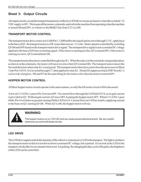
<strong>BC</strong>-<strong>3500</strong> Bill and Coin Changer<br />
Sheet 3: Output Circuits<br />
All output circuits, except the transport transmissive/reflective LED driver circuit, are inactive when the switched +12<br />
VDC supply is OFF. This keeps all the motors, solenoids, and coils in the machine from operating when the machine<br />
is turned ON and OFF, or whenever the RESET line from U21 is LOW.<br />
TRANSPORT MOTOR CONTROL<br />
The transport motor drive comes in to U6B Pin 3. U6B buffers the signal and inverts it through U11C, applying it<br />
to the base of Q5. the transport motor is a DC motor that runs on +12 volts. Motor speed is controlled by switching<br />
Q5 ON and OFF based on the transport motor drive signal. The transport drive signal is not a constant DC voltage<br />
applied to the base of Q5 but a switching signal. If the motor is running too fast, Q5 is turned OFF; if the motor is<br />
running too slow, Q5 is turned back ON.<br />
The transport motor direction is controlled through relay K1. When the relay is in the normal de-energized position,<br />
as shown on the schematic, the motor will run in reverse when Q5 is turned ON. The transport motor runs in the<br />
forward direction when relay K1 is energized. The transport motor direction comes from the processor on Sheet<br />
1 into Pin 5 of U6. It is inverted through U7, then applied to relay K1. Diode D2 suppresses back EMF from K1’s<br />
coil as it de-energizes. D6 and D7 do the same thing for the motor coils when the motor is turned OFF.<br />
HOPPER MOTOR CONTROL<br />
All three hopper motor circuits operate in the same manner, so only the left motor circuit will be discussed.<br />
A low at U11A Pin 1 causes Pin 16 to turn OFF. No current flows through the LED half of U4, so no gate current<br />
is provided to Q3. Without gate current, Q3 stays OFF, keeping the hopper motor OFF. When U11A Pin 1 goes<br />
HIGH, Pin 16 switches to ground, turning ON the LED in U4. Current flows in U4 Pins 4 and 6, supplying current<br />
to the base on Q3, turning Q3 ON. When Q3 is ON, the hopper motor will run.<br />
WARNING:<br />
The hopper motors run on 120 VAC and can cause severe electrical shock. Be very careful<br />
whenever you work with these circuits.<br />
LED DRIVE<br />
The LED drive signal controls the intensity of the reflective-transmissive LED in the transport. The light is similar to<br />
the transport motor in that it is not driven from a constant DC voltage, but is pulsed. If you look at the LED in the<br />
transport, it looks like it is on constant, but it is not. It is pulsing. By changing the duty cycle of the pulse, the brightness<br />
of the LED can be controlled.<br />
4-66 25238801


