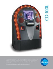
BC-3500 Series - Rowe International
BC-3500 Series - Rowe International
BC-3500 Series - Rowe International

Create successful ePaper yourself
Turn your PDF publications into a flip-book with our unique Google optimized e-Paper software.
Section 4: Troubleshooting<br />
OUT OF SERVICE LAMP<br />
The OUT OF SERVICE lamp is controlled by the switched +12 VDC supply through U7G Pins 7 and 10. Whenever<br />
the switched +12 VDC supply is ON, the power control relay is energized and the OUT OF SERVICE lamp is OFF.<br />
Whenever the switched 12 VDC supply is turned OFF, the power control relay de-energizes and the OUT OF<br />
SERVICE lamp will be lit.<br />
STACKER DRIVE<br />
The stacker drive signal though U12D and U14E is applied to the stacker control board in the stacker. The stacker<br />
drive signal is a 200 ms pulse, just long enough to start the stacker motor and move it off its HOME switch.<br />
DOLLAR COUNTER<br />
The dollar counter is controlled by signals sent through U6D and U7F. A HIGH on U6D Pin 9 turns the counter ON<br />
while a LOW on U6D Pin 9 turns the counter OFF. The counter is pulsed 50 ms ON, 50 ms OFF when counting.<br />
BUCKET DRIVE<br />
All three bucket drive circuits operate in the same manner, so only the left bucket drive circuit will be discussed.<br />
When the bucket circuit is OFF, U11D Pin 4 is LOW, U11D Pin 13 is open, so R106 keeps Q12 OFF. With Q12<br />
OFF, R106 keeps Q8 OFF. When U11D Pin 4 goes HIGH, U11D Pin 13 goes LOW, turning ON Q12. Q12 supples<br />
base current to Q8, turning it ON, which turns ON the bucket coil.<br />
STACKER SOLENOID<br />
When the stacker solenoid is OFF, U6F Pin 13 is LOW, Pin 12 will also be LOW, keeping Q4 OFF. When U6F Pin<br />
13 goes HIGH, Pin 12 will open, allowing base current to Q4 through R83, turning Q4 ON, which turns ON the stacker<br />
solenoid in the stacker. The solenoid controls the flipper which determines whether the bill gets stacked in the upper<br />
or lower box.<br />
COIN LOCKOUT<br />
The coin lockout is controlled by signals sent through U6A and U7E. A HIGH on U6A Pin 1 turns the coin lockout<br />
ON, while a LOW on U6A Pin 1 turns the coin lockout OFF. When the coin lockout is ON, coins may pass through<br />
the coin acceptor to the coins switches.<br />
Sheet 4: Input Circuits<br />
Most of the input circuits are straightforward. A series resistor, usually 100 ohms or 1 K-ohms, and either a .01<br />
or .1 microfarad capacitor to ground provide a little noise filtering. Several inputs have pull up resistors.<br />
Seven inputs from P4 are connected to A/D conversion inputs on the processor. All the other inputs are digital signals.<br />
The circuits involving U17A, U17B, Q14, and Q16 convert analog inputs to digital signals.<br />
25238801 4-67