BC-3500 Series - Rowe International
BC-3500 Series - Rowe International
BC-3500 Series - Rowe International

You also want an ePaper? Increase the reach of your titles
YUMPU automatically turns print PDFs into web optimized ePapers that Google loves.
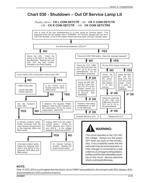
Section 4: Troubleshooting<br />
Chart 030 - Shutdown – Out Of Service Lamp Lit<br />
Display shows: CK L COIN DETCTR – OR – CK C COIN DETCTR<br />
– OR – CK R COIN DETCTR – OR – CK COIN DETCTRS<br />
One or more of the coin photodetectors is, or was, giving an incorrect signal. This<br />
happened when the bill changer was in STANDBY. An incorrect change load may be in<br />
one of the buckets, or one of the hopper motors may have been running in standby mode.<br />
Are all three photodetector LED's lit?<br />
Check the LED. Check the<br />
wiring to the LED in the back of<br />
the dispenser. Replace any unlit<br />
LED with the part number<br />
indicated in the Parts Catalog.<br />
Is the +5VDC LED on the power control center ON?<br />
NO<br />
Refer to the chart<br />
+5VDC FAILURE<br />
+5VDC LED OUT<br />
Are the transport<br />
LED's ON?<br />
YES<br />
NO<br />
NO<br />
Is the +5VDC much<br />
brighter than the other<br />
three LED's?<br />
NO<br />
YES<br />
YES<br />
A defective +5V regulator VR802.<br />
Replace it with the part indicated in<br />
the components list for the power<br />
supply board. See NOTE.<br />
YES<br />
Press the FUNCTION button. Does this message reappear?<br />
NO<br />
Check the O/G, O/BR,<br />
and O/B wires from the<br />
CCC (J4 & J5) to the<br />
photodetector for an<br />
intermittent connection.<br />
IF OK<br />
Check the B/R, BR,<br />
and B/Y wires from<br />
the CCC (P1) to the<br />
hopper motors for<br />
an intermittent short<br />
to Ground. See<br />
WARNING.<br />
IF OK<br />
Possible intermittent<br />
photodetector or LED<br />
on the dispenser.<br />
IF OK<br />
YES<br />
Do any of the hopper motors run?<br />
NO<br />
Check the<br />
operation of<br />
the photodetector.<br />
See Section<br />
3 of this<br />
manual.<br />
IF OK<br />
Check the continuity<br />
of O/G, O/B, and<br />
O/BR wires from the<br />
CCC (J4 & J5) to<br />
the photodetector.<br />
IF OK<br />
YES<br />
Check the B/R,<br />
BR, and B/Y<br />
wires from the<br />
CCC (P1) to the<br />
hopper motor<br />
for a short to<br />
Ground. See<br />
WARNING.<br />
IF OK<br />
Possible defective CCC.<br />
Replace the CCC.<br />
A harness problem exists.<br />
Check continuity from the<br />
main harness terminal block<br />
to the dispenser (Blue and<br />
Black wires).<br />
A harness problem exists.<br />
Check the continuity from<br />
J203-2 and J202-8 to the<br />
dispenser P402 (Blue and<br />
Black wires).<br />
Unplug J203 from the power<br />
control center. Check for<br />
+5VDC between pins J203-2<br />
and J202-8. Is the voltage<br />
between 4.5VDC and 5.5VDC?<br />
YES<br />
NO<br />
An internal harness<br />
problem. Replace the<br />
power control center.<br />
WARNING:<br />
This circuit operates on the 120 VAC<br />
line voltage. Always turn the power<br />
OFF when you work on this circuitry.<br />
Also, if any possibility exists that the<br />
wall outlet may be wired backward, or<br />
if the changer is connected to a wall<br />
outlet via a 2-prong grounding adaptor,<br />
pull the cord from the outlet before working<br />
on this circuit. Serious electrical<br />
shock could result otherwise.<br />
NOTE:<br />
If the +5 VDC LED is much brighter than the others, due to VR801 being defective, the transport cell LEDs, display LEDs,<br />
and photodetector LEDs could be burned out.<br />
25238801 4-33