BC-3500 Series - Rowe International
BC-3500 Series - Rowe International
BC-3500 Series - Rowe International

Create successful ePaper yourself
Turn your PDF publications into a flip-book with our unique Google optimized e-Paper software.
<strong>BC</strong>-<strong>3500</strong> Bill and Coin Changer<br />
13. Perform this step only if you set the stacker mode to “SEP” in the above step. To assign the bills to the upper<br />
or lower bill box, press the VALUE button to go through each denomination you have set to “YES” for<br />
acceptance, and push either the ^ or button to stack these bills in either the “UPPER” or “LOWER” bill boxes.<br />
^<br />
14. Press the FUNCTION button once and the display will show “BILL B CHECK ON” or “OFF”. Use the ^ or<br />
button to select either ON or OFF. This is a security check made during the bill validation process. <strong>Rowe</strong><br />
recommends the “ON” setting for all but the most extreme circumstances where a very high percentage of bills<br />
are rejected with Code “B” (see Section 4).<br />
15. Press the FUNCTION button once and the display will show “BILL TEST OFF”. Use the ^ or<br />
OFF.<br />
^<br />
^<br />
button to select<br />
16. Setup is complete! Place the PROGRAMMING switch back down to the “NORMAL” mode. The display will<br />
show “STORING NEW DATA”, and then the “walking dash” will appear. Fill the hoppers with quarters, do<br />
a test vend from each of the test switches: left, center, and right (located on the power control center), and the<br />
job is completed.<br />
Normal Setup<br />
This procedure follows the “beginning-to-end” setup sequence. You should follow this procedure and use it until<br />
you are familiar with the ten groups of setup options. Once you are familiar with these options, you can easily skip<br />
over the options that you do not wish to change or display.<br />
Key Information<br />
In the step-by-step procedure that follows, key setup information follows many of the numbered steps. This<br />
information will be very helpful, but it can be skipped. Key information paragraphs are indicated by a small to<br />
the left of the key paragraph.<br />
Turning the Power On<br />
1. Be sure the PROGRAMMING/NORMAL switch on the CCC is in the NORMAL position, then turn the power<br />
switch ON. Three of the four voltage LED’s on the power control center should now be ON. The +40 VDC<br />
LED will be OFF. The OUT OF SERVICE light will be lit.<br />
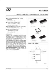
2. The message “ROWE FAST PAY” will be followed by “VERSION XX” on the display. XX is the version<br />
number and should match the version number on the EPROM label, which is visible through the cover of<br />
the CCC.<br />
3. The message “CHECKSUM XXXX” will briefly appear on the display. XXXX is the 16-bit EPROM checksum.<br />
4. Next, the “RAM TEST PASSED” (or “FAILED”) message will briefly display. If the word FAILED appears, the<br />
changer will remain in the OUT OF SERVICE mode.<br />
5. When the “RAM TEST PASSED” message disappears, the CHECKING SYSTEM/SYSTEM CHECK OK<br />
“walking dash” will appear. The +40 VDC LED will light and the OUT OF SERVICE light will turn OFF.<br />
2-8 25238801