BC-3500 Series - Rowe International
BC-3500 Series - Rowe International
BC-3500 Series - Rowe International

You also want an ePaper? Increase the reach of your titles
YUMPU automatically turns print PDFs into web optimized ePapers that Google loves.
Section 3: Routine Service<br />
3. Turn the transport over and connect the Common lead of a voltmeter to P701, Pin 10. Connect the other lead<br />
to P701, Pin 9. Turn the transport motor drive shaft very slowly by hand. The meter should alternately read<br />
voltages below 0.7 VDC then above 3.8 VDC.<br />
4. One rotation of the motor drive shaft will produce 100 pulses.<br />
5. If you were using the Anti-Pullback feature, be sure to re-enable it.<br />
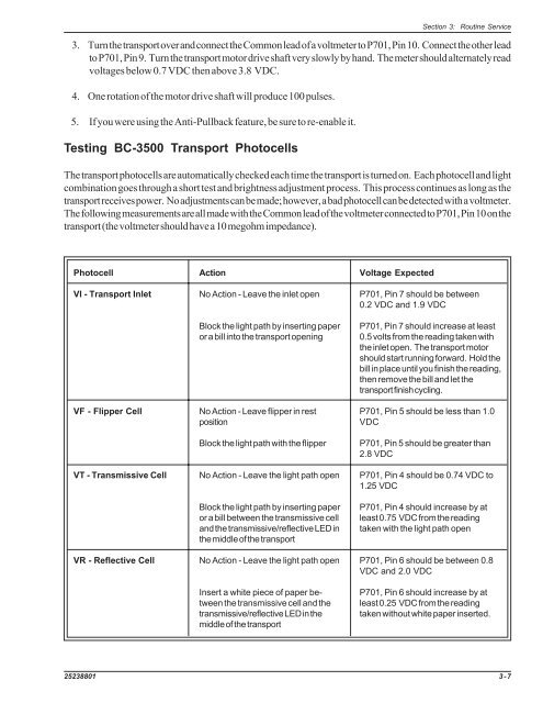
Testing <strong>BC</strong>-<strong>3500</strong> Transport Photocells<br />
The transport photocells are automatically checked each time the transport is turned on. Each photocell and light<br />
combination goes through a short test and brightness adjustment process. This process continues as long as the<br />
transport receives power. No adjustments can be made; however, a bad photocell can be detected with a voltmeter.<br />
The following measurements are all made with the Common lead of the voltmeter connected to P701, Pin 10 on the<br />
transport (the voltmeter should have a 10 megohm impedance).<br />
Photocell<br />
VI - Transport Inlet<br />
VF - Flipper Cell<br />
VT - Transmissive Cell<br />
VR - Reflective Cell<br />
Action<br />
No Action - Leave the inlet open<br />
Block the light path by inserting paper<br />
or a bill into the transport opening<br />
No Action - Leave flipper in rest<br />
position<br />
Block the light path with the flipper<br />
No Action - Leave the light path open<br />
Block the light path by inserting paper<br />
or a bill between the transmissive cell<br />
and the transmissive/reflective LED in<br />
the middle of the transport<br />
No Action - Leave the light path open<br />
Insert a white piece of paper between<br />
the transmissive cell and the<br />
transmissive/reflective LED in the<br />
middle of the transport<br />
Voltage Expected<br />
P701, Pin 7 should be between<br />
0.2 VDC and 1.9 VDC<br />
P701, Pin 7 should increase at least<br />
0.5 volts from the reading taken with<br />
the inlet open. The transport motor<br />
should start running forward. Hold the<br />
bill in place until you finish the reading,<br />
then remove the bill and let the<br />
transport finish cycling.<br />
P701, Pin 5 should be less than 1.0<br />
VDC<br />
P701, Pin 5 should be greater than<br />
2.8 VDC<br />
P701, Pin 4 should be 0.74 VDC to<br />
1.25 VDC<br />
P701, Pin 4 should increase by at<br />
least 0.75 VDC from the reading<br />
taken with the light path open<br />
P701, Pin 6 should be between 0.8<br />
VDC and 2.0 VDC<br />
P701, Pin 6 should increase by at<br />
least 0.25 VDC from the reading<br />
taken without white paper inserted.<br />
25238801 3-7