

8x300 design guide - Al Kossow's Bitsavers - Trailing-Edge
8x300 design guide - Al Kossow's Bitsavers - Trailing-Edge
8x300 design guide - Al Kossow's Bitsavers - Trailing-Edge

Create successful ePaper yourself
Turn your PDF publications into a flip-book with our unique Google optimized e-Paper software.
~<br />
2.1 CPU ARCHITECTURE<br />
Figure 2-1 is a simplified block diagram of the Signetics 8X300<br />
illustrating the major internal functional blocks and data paths of<br />
the device. As is shown in the illustration, the device includes an<br />
Arithmetic Logic Unit (ALU), eight 8-bit working registers, logic for<br />
rotate and mask of data, logic for shifting and merging of data,<br />
decode and control logic, an address register, a program counter and<br />
an instruction register.<br />
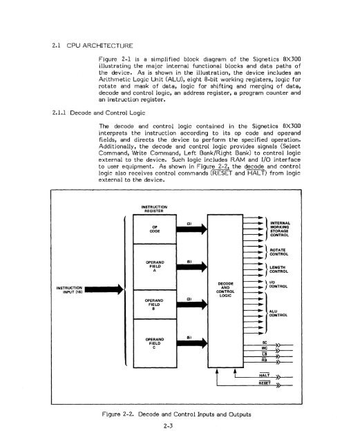
2.1.1 Decode and Control Logic<br />
The decode and control logic contained in the Signetics 8X300<br />
interprets the instruction according to its op code and operand<br />
fields, and directs the device to perform the specified operation.<br />
Additionally, the decode and control logic provides signals (Select<br />
Command, Write Command, Left Bank/Right Bank) to control logic<br />
external to the device. Such logic includes RAM and I/O interface<br />
to user equipment. As shown in Figure 2-2, the decode and control<br />
logic also receives control commands (RESET and HALT) from logic<br />
external to the device.<br />
INSTRUCTION<br />
INPUT (16)<br />
~<br />
INSTRUCTION<br />
REGISTER<br />
OP<br />
WORKING<br />
CODE<br />
,.<br />
- STORAGE<br />
--·<br />
CONTROL<br />
- } ROTATE<br />
CONTROL<br />
..<br />
OPERAND (5)<br />
....<br />
FIELD<br />
-<br />
-'" } LENGTH<br />
A ,. CONTROL<br />
..<br />
DECODE<br />
} I/O<br />
AND<br />
CONTROL<br />
CONTROL<br />
LOGIC<br />
·-<br />
(3)<br />
OPERAND .... --<br />
~<br />
FIELD<br />
B ,.<br />
- ALU<br />
(3) .... - } INTERNAL<br />
(5)<br />
....<br />
-<br />
.. > CONTROL<br />
-<br />
- -'"<br />
OPERAND<br />
FIELD<br />
sc<br />
C ,.<br />
WC<br />
t t<br />
'r--<br />
~<br />
LB<br />
~>--<br />
RB<br />
>>--<br />
HALT<br />
RESET<br />
:~<br />
Figure 2-2. Decode and Control Inputs and Outputs<br />
2-3


