

8x300 design guide - Al Kossow's Bitsavers - Trailing-Edge
8x300 design guide - Al Kossow's Bitsavers - Trailing-Edge
8x300 design guide - Al Kossow's Bitsavers - Trailing-Edge

Create successful ePaper yourself
Turn your PDF publications into a flip-book with our unique Google optimized e-Paper software.
.... BITS 0-4<br />
MUX<br />
C<br />
_BITS 3-7<br />
IR<br />
BITS 0-4<br />
BITS 0-4<br />
~<br />
ADDRESS<br />
BITS<br />
0-12<br />
BITS 5-7<br />
ADDRESS<br />
MUX<br />
REGISTER<br />
... B<br />
"<br />
~<br />
""'-<br />
• BITS 6-7<br />
INCREMENT<br />
LOGIC<br />
..of BITS 5-7<br />
...<br />
PROGRAM<br />
COUNTER<br />
~<br />
1<br />
LOAD<br />
"<br />
~<br />
BIT88-12<br />
MUX<br />
A<br />
"<br />
~<br />
"<br />
• I,"""<br />
I I<br />
BITS BITS<br />
37 02<br />
-..<br />
FROM<br />
ALU<br />
1<br />
INHIBIT<br />
BITS 8-12<br />
I<br />
LOAD<br />
2.1.4 Bus Structure and Control<br />
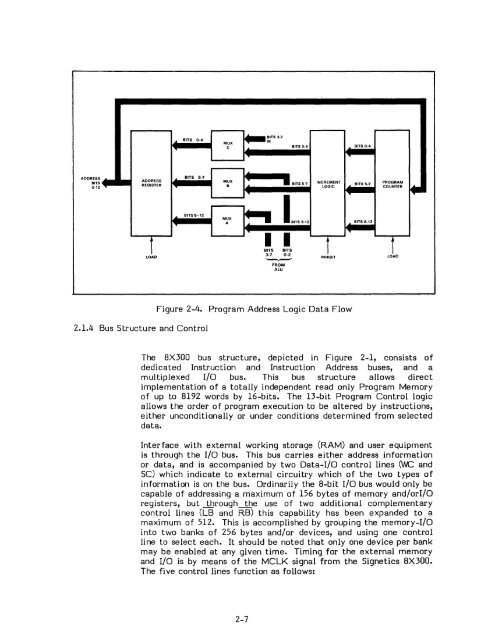
Figure 2-4. Program Address Logic Data Flow<br />
The 8X300 bus structure, depicted in Figure 2-1, consists of<br />
dedicated Instruction and Instruction Address buses, and a<br />
multiplexed I/O bus. This bus structure allows direct<br />
implementation of a totally independent read only Program Memory<br />
of up to 8192 words by 16-bits. The 13-bit Program Control logic<br />
allows the order of program execution to be altered by instructions,<br />
either unconditionally or under conditions determined from selected<br />
data.<br />
Interface with external working storage (RAM) and user equipment<br />
is through the I/o bus. This bus carries either address information<br />
or data, and is accompanied by two Data-I/O control lines (WC and<br />
SC) which indicate to external circuitry which of the two types of<br />
information is on the bus. Ordinarily the 8-bit I/o bus would only be<br />
capable of addressing a maximum of 156 bytes of memory and/orI/O<br />
registers, but --1brough--1be use of two additional complementary<br />
control lines (LB and RB) this capability has been expanded to a<br />
maximum of 512. This is accomplished by grouping the memory-I/O<br />
into two banks of 256 bytes and/or devices, and using one control<br />
line to select each. It should be noted that only one device per bank<br />
may be enabled at any given time. Timing for the external memory<br />
and I/o is by means of the MCLK signal from the Signetics 8X300.<br />
The five control lines function as follows:<br />
2-7


