

8x300 design guide - Al Kossow's Bitsavers - Trailing-Edge
8x300 design guide - Al Kossow's Bitsavers - Trailing-Edge
8x300 design guide - Al Kossow's Bitsavers - Trailing-Edge

Create successful ePaper yourself
Turn your PDF publications into a flip-book with our unique Google optimized e-Paper software.
INSTRUCTION •••• tI<br />
INPUT<br />
INSTRUCTION<br />
LATCH<br />
OUTPUT<br />
PHASE<br />
LB/RB<br />
FIRST<br />
QUARTER-CYCLE ______ --1<br />
INPUT -<br />
PHASE<br />
..... _"<br />
--<br />
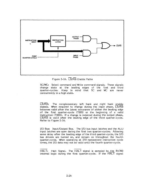
Figure 2-16. LB/RB Enable Paths<br />
SC/WC: Select command and Write command signals. These signals<br />
change state at the leading edges of the first and third<br />
quarter-cycles. Keep in mind that SC and WC are never<br />
concurrently in a high state.<br />
LB/RB: The complementary left bank and right bank enable<br />
signals. When required to change during the input phase, LB/RB<br />
becomes valid after the latest occurance of either the leading edge<br />
of the first quarter-cycle (TIBS) or the beginning of a valid<br />
instruction (TIIBS). If a change is required during the output phase,<br />
LB/RB is valid after the leading edge of the third quarter-cycle.<br />
Refer to Figure 2-16.<br />
I/o Bus: Input/Output Bus. The I/O bus input latches and the ALU<br />
input latches are open during the first two quarter-cycles. <strong>Al</strong>lowing<br />
some delay after the leading edge of the third quarter-cycle, the I/O<br />
bus drivers are turned on, and remain on throughout the fourth<br />
quarter-cycle. When operating at 250 nanosecond instruction cycle<br />
times, the I/O data may not be valid until the fourth quarter-cycle.<br />
HAL T: Halt Signal. The HALT signal is sampled by': the 8X300<br />
internal logic during the first quarter-cycle. If the HALT signal<br />
2-24


