

8x300 design guide - Al Kossow's Bitsavers - Trailing-Edge
8x300 design guide - Al Kossow's Bitsavers - Trailing-Edge
8x300 design guide - Al Kossow's Bitsavers - Trailing-Edge

Create successful ePaper yourself
Turn your PDF publications into a flip-book with our unique Google optimized e-Paper software.
1<br />
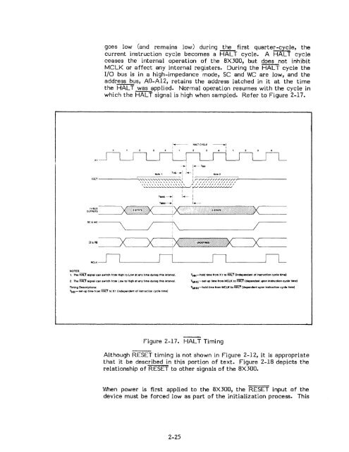
goes low (and remains low) during ~ first quarter-cycie, the<br />
current instruction cycle becomes a HALT cycle. A HAL cycle<br />
ceases the internal operation of the 8X300, but does not inhibit<br />
MCLK or affect any internal registers. During the 'RACT cycle the<br />
I/O bus is in a high-impedance mode, SC and WC are low, and the<br />
address bus, AO-A12, retains the address latched in it at the time<br />
the HALT was applied. Normal operation resumes with the cycle in<br />
which the HALf signal is high when sampled. Refer to Figure 2-17.<br />
,- HALT CYCLE _I<br />
I<br />
I<br />
1<br />
x,<br />
_I I..--THH<br />
1 I<br />
Not. 1 THS_I 1- 1 Not. 2<br />
=:-:r-:-:r:-:r:-::r:-:r:-::r-::r::r::rr~r~r;::r:=-:r:-::,~--------<br />
\\\\\\.\\\"\\\\', "//////////1111/<br />
HALT ------~~,""\::::;:-'\:::::;,:::::;""\-::,:::"~""\~,~,~,~,~,::::;,:::::" i ir-<br />
\\\\\\\\\\\\\\\\\ /1 /1/11/11////1//<br />
'-~'-'-'-'-'-'-'--'-'--'-'-'-\....fI-'---I t'-' JJ-/JJ~.../JJJJJJ<br />
TMHs-1<br />
TMHH-l<br />
1 I<br />
I-I<br />
I<br />
1-<br />
OU~~~~~_--J~D(~-----'-J: )0~~Z~~,----__<br />
SC&WC-_______ \ / :\ /<br />
1<br />
I<br />
1<br />
~&~ ______ ~)(~ ____ ~)(L ____ ~:~~----~)(L-----<br />
I<br />
MCLK<br />
NOTES<br />
1. The HALT signal can switch from High to Low at any time during this interval. TI+i-hold time from XI to HALl (independent of instruction cycle time)<br />
2. The HALT signal can switch from Low to High at any time during this interval.<br />
Timing Descriptions:<br />
THS-set-up time Irom HALT to XI (independent of instruction cycle time)<br />
TMHS-set-up time from MCLK to HALl (dependent upon instruction cycle time)<br />
TMI+i-hold time from MCLK to HALl (dependent upon instruction cycle time)<br />
Figure 2-17 • HALT Timing<br />
<strong>Al</strong>though RESET timing is not shown in Figure 2-12, it is appropriate<br />
that it be described in this portion of text. Figure 2-18 depicts the<br />
relationship of RESET to other signals of the 8X300.<br />
When power is first applied to the 8X300, the RESET input of the<br />
device must be forced low as part of the initialization process. This<br />
2-25


