

8x300 design guide - Al Kossow's Bitsavers - Trailing-Edge
8x300 design guide - Al Kossow's Bitsavers - Trailing-Edge
8x300 design guide - Al Kossow's Bitsavers - Trailing-Edge

Create successful ePaper yourself
Turn your PDF publications into a flip-book with our unique Google optimized e-Paper software.
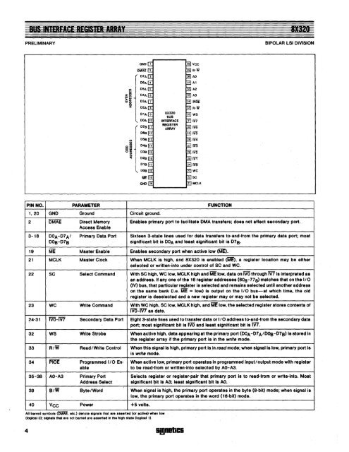
BUS INtERfACE REGISTER ARRAY<br />
PRELIMINARY<br />
IWi21<br />
BIPOLAR LSI DIVISION<br />
ffi<br />
><br />
w<br />
GND 1<br />
:: 3<br />
D5A<br />
r<br />
DMAE 2<br />
:::·<br />
1<br />
D1A 9<br />
DOA 10<br />
8X320<br />
BUS<br />
INTERFACE<br />
REGISTER<br />
ARRAY<br />
I/)<br />
~<br />
01/)<br />
ow<br />
°8<br />
c<br />
PIN NO.<br />
PARAMETER<br />
1,20 GND Ground<br />
2 DMAE Direct Memory<br />
Access Enable<br />
3-18 DOA-D7AI Primary Data Port<br />
DOB-D7B<br />
'-<br />
19 ME Master Enable<br />
21 MCLK Master Clock<br />
22 SC Select Command<br />
23 WC Write Command<br />
24-31 IVO-IV7 Secondary Data Port<br />
32 WS Write Strobe<br />
33 RIW Read I Write Control<br />
34 PiCE Programmed 110 Enable<br />
35-38 AO-A3 Primary Port<br />
Address Select<br />
39 B/W Byte I Word<br />
40 VCC Power<br />
Circuit ground.<br />
FUNCTION<br />
Enables primary port to facilitate DMA transfers; does not affect secondary port.<br />
Sixteen 3-state lines used for data transfers to-and-from the primary data port; most<br />
significant bit is DOA and least significant bit is D7B.<br />
Enables secondary port when active low (ME).<br />
When MCLK is highj and 8X320 is enabled (ME), a register location may be either<br />
selected or written-into under control of SC and WC.<br />
With SC high, WC low, MCLK high and ME low, data on IVO through m is interpreted as<br />
an address. If anyone of the 16 register addresses (608-778) matches that on the 1/0<br />
(IV) bus, that particular register is selected and remains selected until another address<br />
on the same bank (i.e. ME = low) is output on the 1/0 bus-at which time, the old<br />
register is deselected and a new register mayor may not be selected.<br />
With WC high, SC low, MCLK high, and ME low, the selected register stores contents of<br />
IVO-IV7 as data.<br />
Eight 3-state lines used to transfer data or 110 address to-and-from the secondary data<br />
port;· most significant bit is IVO and least significant bit is M.<br />
When active high, data appearing at the primary port (DOA-D7 A/DOB-D7B) is stored in<br />
the register array if the primary port is in the write mode.<br />
When this signal is high, primary port is ,in read mode; when signal is low, primary port is<br />
in write mode.<br />
When active low, primary port operates in programmed input I output mode with register<br />
to be read-from or written-into selected by AO-A3.<br />
Selects register or register-pair that primary port is to read-from or write-into. Most<br />
significant t;»it is A3; least significant bit is AO.<br />
When Signal is high, the primary port operates in the byte (8-bit) mode; when Signal is<br />
low, the primary port operates in the word (16-bit) mode.<br />
+5 volts.<br />
<strong>Al</strong>l barred symbols (OMAE. etc.) denote signals that are asserted (or active) when low<br />
(logical 0); signals that are not barred are aSlerted in the .tligh state (logical 1).<br />
4 Si!jII!IICS


