

8x300 design guide - Al Kossow's Bitsavers - Trailing-Edge
8x300 design guide - Al Kossow's Bitsavers - Trailing-Edge
8x300 design guide - Al Kossow's Bitsavers - Trailing-Edge

You also want an ePaper? Increase the reach of your titles
YUMPU automatically turns print PDFs into web optimized ePapers that Google loves.
.. ----------- L<br />
MICIOCQNJRQLLER<br />
81311<br />
BIPOLAR LSI DIVISION<br />
Rotate (R) and length (l) Field: The three-bit R / L field<br />
performs one of two functions, speCifying either the field<br />
length (L) or a right-rotate (R). For a given instruction, the<br />
specified function depends upon the contents of the source<br />
(S) and destination (D) fields.<br />
• When an internal register is specified by both the source<br />
and destination fields, the (R) field is invoked and it specifies<br />
a right-rotate of the data specified in the (S) field-see<br />
accompanying diagram. The source-register data (up to<br />
eight-bits) is right-rotated within one instruction cycle. (The<br />
right-rotate function is implemented on the bus and not in the<br />
source register.)<br />
RIGHT-ROTATE FUNCTION<br />
Bit Position - 0 1 2 3 4 5 6 7<br />
Pi' , t'·I+i]<br />
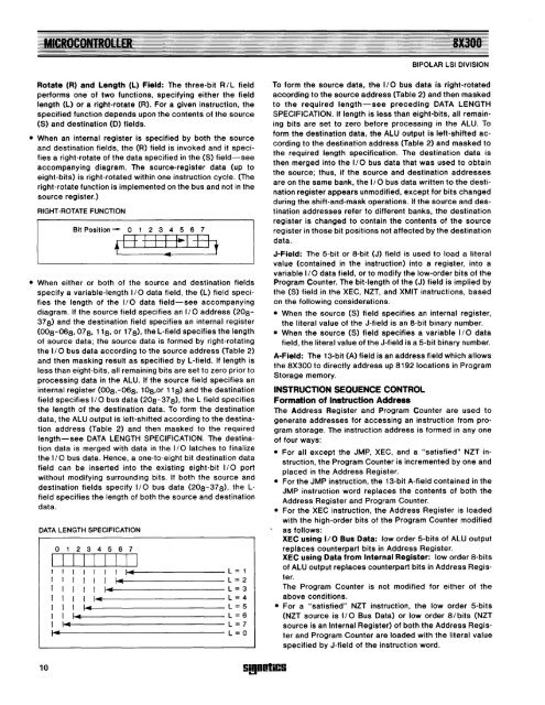
• When either or both of the source and destination fields<br />
specify a variable-length I/O data field, the (L) field specifies<br />
the length of the I/O data field-see accompanying<br />
diagram. If the source field specifies an I/O address (20a-<br />
37 a) and the destination field specifies an internal register<br />
(00a-06a, 07 a, 11a, or 17 a), the L-field specifies the length<br />
of source data; the source data is formed by right-rotating<br />
the I/O bus data according to the source address (Table 2)<br />
and then masking result as specified by L-field. If length is<br />
less than eight-bits, all remaining bits are set to zero prior to<br />
processing data in the ALU. If the source field specifies an<br />
internal register (00a,-06a, 10a,or 11a) and the destination<br />
field specifies I/O bus data (20a-37 a), the L field specifies<br />
the length of the destination data. To form the destination<br />
data, the ALU output is left-shifted according to the destination<br />
address (Table 2) and then masked to the required<br />
length-see DATA LENGTH SPECIFICATION. The destination<br />
data is merged with data in the I/O latches to finalize<br />
the I/O bus data. Hence, a one-to-eight bit destination data<br />
field can be inserted into the existing eight-bit I/O port<br />
without modifying surrounding bits. If both the source and<br />
destination fields specify I/O bus data (20a - 37 a), the L<br />
field specifies the length of both the source and destination<br />
data.<br />
DATA LENGTH SPECIFICATION<br />
o 1 2 3 4 5 6 7<br />
I I I I I I I I I<br />
I I 1-011<br />
= 1<br />
I I 1 I.. L = 2<br />
I I 1 I_ L = 3<br />
1 1 I.. L = 4<br />
1 I_ L = 5<br />
1 I... L = 6<br />
I I'" L = 7<br />
I" L = 0<br />
To form the source data, the I/O bus data is right-rotated<br />
according to the source address (Table 2) and then masked<br />
to the required length-see preceding DATA LENGTH<br />
SPECIFICATION. If length is less than eight-bits, all remaining<br />
bits are set to zero before processing in the ALU. To<br />
form the destination data, the ALU output is left-shifted according<br />
to the destination address (Table 2) and masked to<br />
the required length speCification. The destination data is<br />
then merged into the I/O bus data that was used to obtain<br />
the source; thus, if the source and destination addresses<br />
are on the same bank, the I/O bus data written to the destination<br />
register appears unmodified, except for bits changed<br />
during the shift-and-mask operations. If the source and destination<br />
addresses refer to different banks, the destination<br />
register is changed to contain the contents of the source<br />
register in those bit positions not affected by the destination<br />
data.<br />
J-Field: The 5-bit or a-bit (J) field is used to load a literal<br />
value (contained in the instruction) into a register, into a<br />
variable I/O data field, or to modify the low-order bits of the<br />
Program Counter. The bit-length of the (J) field is implied by<br />
the (S) field in the XEC, NZT, and XMIT instructions, based<br />
on the following considerations.<br />
• When the source (S) field specifies an internal register,<br />
the literal value of the J-field is an a-bit binary number.<br />
• When the source (S) field specifies a variable I/O data<br />
field, the literal value of the J-field is a 5-bit binary number.<br />
A-Field: The 13-bit (A) field is an address field which allows<br />
the aX300 to directly address up a192 locations in Program<br />
Storage memory.<br />
INSTRUCTION SEQUENCE CONTROL<br />
Formation of Instruction Address<br />
The Address Register and Program Counter are used to<br />
generate addresses for accessing an instruction from program<br />
storage. The instruction address is formed in anyone<br />
of four ways:<br />
• For all except the JMP, XEC, and a "satisfied" NZT instruction,<br />
the Program Counter is incremented by one and<br />
placed in the Address Register.<br />
• For the JMP instruction, the 13-bit A-field contained in the<br />
JMP instruction word replaces the contents of both the<br />
Address Register and Program Counter.<br />
• For the XEC instruction, the Address Register is loaded<br />
with the high-order bits of the Program Counter modified<br />
as follows:<br />
XEC using 1/0 Bus Data: low order 5-bits of ALU output<br />
replaces counterpart bits in Address Register.<br />
XEC using Data from Internal Register: low order a-bits<br />
of ALU output replaces counterpart bits in Address Register.<br />
The Program Counter is not modified for either of the<br />
above conditions.<br />
• For a "satisfied" NZT instruction, the low order 5-bits<br />
(NZT source is I/O Bus Data) or low order a/bits (NZT<br />
source is an Internal Register) of both the Address Register<br />
and Program Counter are loaded with the literal value<br />
specified by J-field of the instruction word.<br />
10 Si!l00liC!i


