Aufbau einer gepulsten Quelle polarisierter Elektronen - Institut für ...
Aufbau einer gepulsten Quelle polarisierter Elektronen - Institut für ...
Aufbau einer gepulsten Quelle polarisierter Elektronen - Institut für ...

Sie wollen auch ein ePaper? Erhöhen Sie die Reichweite Ihrer Titel.
YUMPU macht aus Druck-PDFs automatisch weboptimierte ePaper, die Google liebt.
16 P. Hartmann et al. / Nucl. Instr. and Meth. in Phys. Res. A 379 (1996) 15 – 20<br />
what severely lowers the current of polarized electrons<br />
available for experiments at MAMI. One could<br />
gain in capture efficiency by chopping the beam at<br />
the cathode already. Illumination of the cathode with<br />
a pulsed light beam synchronuous to the accelerator<br />
rf would greatly enhance the capture, if short enough<br />
electron bunches were produced in this way. An increase<br />
in the accelerated beam current without a decrease<br />
of the cathode lifetime could be achieved. In case of<br />
MAMI the pulse duration should be less than 65 ps.<br />
Theoretical calculations based on a diffusion model<br />
[9,10] predict very long cathode response times in the<br />
order of nanoseconds. Recent Monte Carlo studies taking<br />
into account solid state scattering mechanisms<br />
[11] give response times of 270 ps. Experimental investigations<br />
by Phillips et al. [12] using a streak camera<br />
method find bunchlengths of electrons emitted<br />
from GaAs cathodes between 8 and 71 ps. Investigations<br />
by Aleksandrov et al. [13] with circular rfdeflection<br />
give an upper limit of 40 ps for bunches<br />
emitted from GaAs cathodes.<br />
The present work describes an apparatus which not<br />
only refines these findings, but extends the method to<br />
measurements of energy spread and phase resolved<br />
polarization.<br />
2. The Experimental Setup<br />
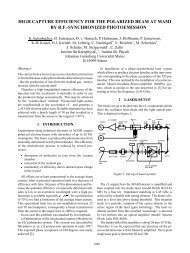
A sketch of the experimental facility at MAMI is<br />
shown in Figure 2. It consists of an electron gun, a<br />
beam transport system, a radiofrequency deflector resonator<br />
followed by an electron spectrometer and a<br />
Mottdetector for polarization analysis. By opening a<br />
plug in the spectrometer the beam can be injected into<br />
the injection line of MAMI.<br />
2.1. Electron gun<br />
laser beam coming from below. The laser spot at the<br />
cathode has a diameter of 0.6 mm. The electrons are<br />
extracted antiparallel to the laser beam by a 100 kV<br />
accelerating voltage. Details of the design may be<br />
found in [8,14].<br />
In this work a strained layer GaAs 0:95P 0:05-cathode<br />
purchased from the Ioffe <strong>Institut</strong>e in St. Petersburg<br />
[15] is used. The thickness of the electron emitting<br />
epilayer is 150 nm. The same type of photocathode is<br />
routinely used in the MAMI source of polarized electrons<br />
[8]. Negative electron affinity is achieved by a<br />
(Cs + O)-layer on the cathode surface [9]. A quantum<br />
efficiency of 5 10 ;4 has been obtained at a wavelength<br />
of 836 nm of the irradiating light.<br />
2.2. Laser system<br />
A Kerr-lens modelocked Titanium-Sapphire Laser<br />
[16] is used as the light source. The light pulse duration<br />
is measured with an autocorrelator [17]. Fig.<br />
3 shows an autocorrelation trace of the laser pulses.<br />
The duration is 105 fs (FWHM), assuming a standard<br />
(sech) 2 pulse shape. The laser is running at a repetition<br />
rate of 76.5406 MHz and is phaselocked to<br />
the 32 nd subharmonic of the MAMI radiofrequency<br />
of 2.4493 GHz, using a Coherent Synchro-Lock unit<br />
(see Fig 4). The laser beam intensity is adjusted with a<br />
pair of Glan-Foucault-prisms. Circular light polarization<br />
is obtained with help of a Pockelscell in the beam.<br />
The voltage across the Pockelscell may be reversed to<br />
switch from positive to negative helicity. The degree<br />
of circular polarization observed is 0.995 0.001 for<br />
each helicity.<br />
200<br />
The electron gun consists of a triode system shown in<br />
the inset of Fig. 2. Photoemission is excited by an incident<br />
Faradaycup<br />
Mottdetector<br />
;;;;;;;;;;<br />
yyyyyyyyyy<br />
yyyy;;;;;;;;;;<br />
yyyyyyyyyy<br />
yyyy;;;;;;;;;;<br />
yyyyyyyyyy ;;;;; yyyyy<br />
;;;;;;;;;<br />
yyyyyyyyy<br />
;;;;;;;;;;<br />
yyyyyyyyyy ;;;;;;;;;;<br />
yyyyyyyyyy<br />
;;;;;;;;;<br />
yyyyyyyyy<br />
;;;;;;;;;;<br />
yyyyyyyyyy ;;;;;;;;;;<br />
yyyyyyyyyy<br />
;;;;;;;;;<br />
yyyyyyyyy<br />
;;;;;;;;;;<br />
yyyyyyyyyy<br />
-100 kV<br />
;;;;;;;;;;<br />
yyyyyyyyyy<br />
;;;;;;;;;<br />
yyyyyyyyy<br />
;;;;;;;;;;<br />
yyyyyyyyyy ;;;;;;;;;;<br />
yyyyyyyyyy<br />
;;;;;;;;;<br />
yyyyyyyyy<br />
;;;;;;;;;;<br />
yyyyyyyyyy ;;;;;;;;;;<br />
yyyyyyyyyy<br />
;;;;;;;;;<br />
yyyyyyyyy<br />
;;;;;;;;;;<br />
yyyyyyyyyy ;;;;;;;;;;<br />
yyyyyyyyyy<br />
;;;;;;;;;<br />
yyyyyyyyy<br />
;;;;;;;;;;<br />
yyyyyyyyyy ;;;;;;;;;;<br />
yyyyyyyyyy<br />
;;;;;;;;;<br />
yyyyyyyyy<br />
;;;;;;;;;;<br />
yyyyyyyyyy GaAsP ;;;;;;;;;;<br />
yyyyyyyyyy<br />
;;;;;;;;;<br />
yyyyyyyyy<br />
;;;;;;;;;;<br />
yyyyyyyyyy ;;;;;;;;;;<br />
yyyyyyyyyy<br />
;;;;;;;;;<br />
yyyyyyyyy<br />
;;;;;;;;;;<br />
yyyyyyyyyy ;;;;;;;;;;<br />
yyyyyyyyyy<br />
;;;;;;;;;<br />
yyyyyyyyy<br />
;;;;;;;;;;<br />
yyyyyyyyyy ;;;;;;;;;;<br />
yyyyyyyyyy<br />
;;;;;;;;;<br />
yyyyyyyyy<br />
;;;;;;;;;;<br />
yyyyyyyyyy<br />
;;;;;;;;;<br />
yyyyyyyyy<br />
;;;;;;;;;;<br />
yyyyyyyyyy<br />
;;;;;;;;;<br />
yyyyyyyyy<br />
;;;;;;;;;;<br />
yyyyyyyyyy<br />
;;;;;;;;;<br />
yyyyyyyyy<br />
;;;;;;;;;;<br />
yyyyyyyyyy<br />
;;;;;;;;;<br />
yyyyyyyyy<br />
γ ;;;;;;;;;;<br />
yyyyyyyyyy<br />
e<br />
;;;;;;;;;<br />
yyyyyyyyy ;;;;;;;;;;<br />
yyyyyyyyyy<br />
;;;;;;;;;<br />
yyyyyyyyy ;;;;;;;;;;<br />
yyyyyyyyyy<br />
0 V<br />
;;;;;;;;;<br />
yyyyyyyyy ;;;;;;;;;;<br />
yyyyyyyyyy<br />
;;;;;;;;;<br />
yyyyyyyyy<br />
-50 kV<br />
;;;;;;;;;;<br />
yyyyyyyyyy<br />
;;;;;;;;;<br />
yyyyyyyyy ;;;;;;;;;;<br />
yyyyyyyyyy<br />
;;;;;;;;;<br />
yyyyyyyyy ;;;;;;;;;;<br />
yyyyyyyyyy<br />
;;;;;;;;;<br />
yyyyyyyyy ;;;;;;;;;;<br />
yyyyyyyyyy<br />
Electron<br />
Gun<br />
Signal / a.u.<br />
180<br />
160<br />
140<br />
120<br />
100<br />
80<br />
60<br />
Scanner<br />
Diff. Pump<br />
Spectrometer Deflector<br />
Solenoid<br />
1 m<br />
Triplett<br />
Alphamagnet<br />
Fig. 2. Sketch of the experimental setup<br />
Doublett<br />
γ<br />
40<br />
20<br />
0<br />
0 200 400 600 800 1000 1200 1400<br />
Delay / fs<br />
Fig. 3. Autocorrelation signal of the laser pulses. Assuming<br />
a standard (sech) 2 pulseshape, the pulsewidth<br />
is 105 femtoseconds (FWHM).