Solar Energy Perspectives - IEA
Solar Energy Perspectives - IEA
Solar Energy Perspectives - IEA

Create successful ePaper yourself
Turn your PDF publications into a flip-book with our unique Google optimized e-Paper software.
Chapter 7: <strong>Solar</strong> heat<br />
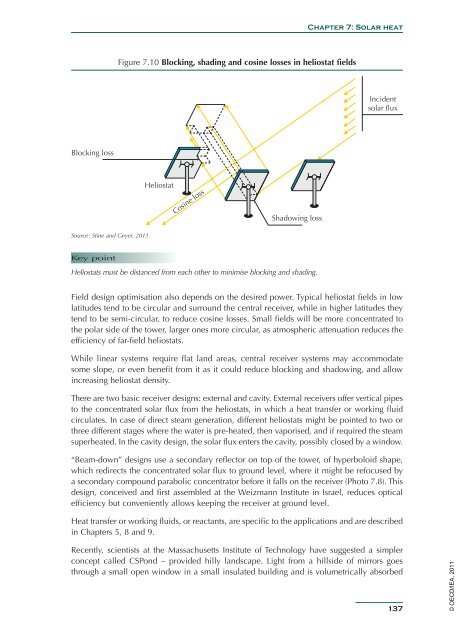
Figure 7.10 Blocking, shading and cosine losses in heliostat fields<br />
Incident<br />
solar flux<br />
Blocking loss<br />
Heliostat<br />
Cosine loss<br />
Shadowing loss<br />
Source: Stine and Geyer, 2011.<br />
Key point<br />
Heliostats must be distanced from each other to minimise blocking and shading.<br />
Field design optimisation also depends on the desired power. Typical heliostat fields in low<br />
latitudes tend to be circular and surround the central receiver, while in higher latitudes they<br />
tend to be semi-circular, to reduce cosine losses. Small fields will be more concentrated to<br />
the polar side of the tower, larger ones more circular, as atmospheric attenuation reduces the<br />
efficiency of far-field heliostats.<br />
While linear systems require flat land areas, central receiver systems may accommodate<br />
some slope, or even benefit from it as it could reduce blocking and shadowing, and allow<br />
increasing heliostat density.<br />
There are two basic receiver designs: external and cavity. External receivers offer vertical pipes<br />
to the concentrated solar flux from the heliostats, in which a heat transfer or working fluid<br />
circulates. In case of direct steam generation, different heliostats might be pointed to two or<br />
three different stages where the water is pre-heated, then vaporised, and if required the steam<br />
superheated. In the cavity design, the solar flux enters the cavity, possibly closed by a window.<br />
“Beam-down” designs use a secondary reflector on top of the tower, of hyperboloid shape,<br />
which redirects the concentrated solar flux to ground level, where it might be refocused by<br />
a secondary compound parabolic concentrator before it falls on the receiver (Photo 7.8). This<br />
design, conceived and first assembled at the Weizmann Institute in Israel, reduces optical<br />
efficiency but conveniently allows keeping the receiver at ground level.<br />
Heat transfer or working fluids, or reactants, are specific to the applications and are described<br />
in Chapters 5, 8 and 9.<br />
Recently, scientists at the Massachusetts Institute of Technology have suggested a simpler<br />
concept called CSPond – provided hilly landscape. Light from a hillside of mirrors goes<br />
through a small open window in a small insulated building and is volumetrically absorbed<br />
137<br />
© OECD/<strong>IEA</strong>, 2011