<strong>Process</strong> <strong>Unit</strong> <strong>73</strong> <strong>LF</strong> limit contacts/controller interface commands, 12–20 setting, 9–31 logbook, 3–3 definition, 17–3 interface commands, 12–7 M main display, definition, 17–3 maint, definition, 17–3 maintenance, 10–7 Maintenance menu, 4–1 definition, 17–3 maintenance passcode definition, 17–3 setting, 8–4 manipulated variable, definition, 17–3 marker setting, 8–2 meas, definition, 17–3 measurement data, 3–2 point of measurement, 3–2 measurement display, 9–12 interface commands, 12–11 measurement lead time, definition, 17–3 measurement point maintenance, 4–2 interface commands, 12–27 measuring capabilities, connections, 9–26 measuring mode, 2–1 definition, 17–3 menu, definition, 17–3 menu level, definition, 17–3 menu structure, 1–3, 2–4 message list, 3–2 definition, 17–3 mounting, 10–1 mounting accessories, list, 13–2 mounting plate, 10–1, 13–2 N NAMUR, definition, 17–3 NAMUR contacts, 9–29 definition, 17–3 interface commands, 12–19 setting, 9–30 neutral zone, 9–33 numeric value change input range, 2–5 input, 2–5 O Operator level, 7–1 definition, 17–3 example, 7–2 operator passcode definition, 17–3 setting, 8–4 opl, 7–1 options, list, 13–1 output 2/controller, interface commands, 12–18 output current 1, interface commands, 12–16 output current 2 interface commands, 12–17 setting, 9–21 output curve bilinear, 9–19 function, 9–20 linear, 9–18 logarithmic, 9–20 trilinear, 9–19 P par, definition, 17–3 parameter setting Administrator level, 8–1 interface commands, 12–29 marker setting, 8–2 passcodes, 8–4 interface commands, 12–9 Operator level, 7–1 Viewing level, 5–1 18–4 Index
Parameter Setting menu, definition, 17–4 passcode protection, definition, 17–4 passcodes factory settings, 8–6 setting, 8–4 point of measurement, 3–3 definition, 17–4 interface commands, 12–9 power output, 9–42 power supply, 9–1, 10–5 probe rinsing, 9–44 information, 9–47 interface commands, 12–24, 12–27 operation, 9–46 setting, 9–47 protective case, 10–1, 13–2 protective hood, 10–1, 13–2 R reference temperature, 9–16 definition, 17–4 reset time, 9–33 resistance measurement, 4–3 interface commands, 12–27 rinsing cycle, 9–44 definition, 17–4 disable, 9–44 rinsing lead time, definition, 17–4 RS 485 interface, 9–49 bus protocol, 12–30 command set, 12–5 contents, 12–1 information, 9–51 interface commands, 12–25, 12–29 point to point, 12–29 setting, 9–51 transmission behavior, 12–4 write protection, 9–50, 12–29 secondary display, 2–1 definition, 17–4 interface commands, 12–11, 12–12 setpoint, 9–33 sign, change, 2–6 span, 9–18 specifications, 14–1 STATUS, interface commands, 12–6 T TC process medium, interface command, 12–13 technical terms, 17–1 temperature alarm, 9–27 interface commands, 12–14 temperature coefficient, definition, 17–4 temperature compensation, 9–13, 9–16 automatic, 9–14 definition, 17–4 disabled, 9–16 linear, 9–16 manual, 9–15 natural waters (EN 27888), 9–16 setting, 9–17 temperature detection, 6–4, 9–13 interface commands, 12–13 temperature probe, connection, 9–14 temperature probe adjustment, 4–5 interface commands, 12–10, 12–27 terminal assignments, 10–6 U ultrapure water with traces of impurity, calibration, 6–9 user interface, 1–1 S scrolling key, definition, 17–4 second rinsing time, definition, 17–4 V VALUE, interface commands, 12–5 view, 5–1 Index 18–5
- Page 1 and 2:
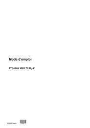
Instruction Manual Process Unit 73
- Page 3 and 4:
Changes for Software Release 6 Proc
- Page 5 and 6:
Safety Information Be sure to read
- Page 7 and 8:
Information on Electromagnetic Comp
- Page 9 and 10:
The representation of a menu in thi
- Page 11 and 12:
Contents Safety Information . . . .
- Page 13 and 14:
9 Capabilities of the Process Unit
- Page 15 and 16:
1 Overview of the Process Unit 73 L
- Page 17 and 18:
vanic isolation optional) allows li
- Page 19 and 20:
2 Operating the Process Unit 73 LF
- Page 21 and 22:
Control Elements Pressing menu key
- Page 23 and 24:
How to select a menu item Press scr
- Page 25 and 26:
How to keep the old setting Pressin
- Page 27 and 28:
3 Diagnostics Menu What you can do
- Page 29 and 30:
How to enter the point of measureme
- Page 31 and 32:
Device Diagnostics What you can do
- Page 33 and 34:
4 Maintenance Menu What you can do
- Page 35 and 36:
Resistance Measurement Press and
- Page 37 and 38:
Temperature Probe Adjustment This f
- Page 39 and 40:
5 Viewing Level What you can do on
- Page 41 and 42:
6 Calibration Why do you have to ca
- Page 43 and 44:
How to select a calibration sequenc
- Page 45 and 46:
Automatic Calibration with Standard
- Page 47 and 48:
Calibration by Manual Entry of Cond
- Page 49 and 50:
Calibration by Entry of Premeasured
- Page 51 and 52:
With TC correction T ref = 25 °C W
- Page 53 and 54:
7 Operator Level What you can do on
- Page 55 and 56:
8 Administrator Level Before commis
- Page 57 and 58:
An Example You want to change the s
- Page 59 and 60:
How to set the administrator passco
- Page 61 and 62:
9 Capabilities of the Process Unit
- Page 63 and 64:
Pt 100/ Pt 1000/ Ni 100 Process Uni
- Page 65 and 66:
wt pk bn gy bu gn rd yw Shi
- Page 67 and 68:
Conductivity Measurement using ZU 0
- Page 69 and 70:
Sensor cable Terminal box ZU 0307 E
- Page 71 and 72:
Sensor cable Terminal box ZU 0307 g
- Page 73 and 74:
Calibration Solution for Automatic
- Page 75 and 76:
Manual Temperature Compensation Man
- Page 77 and 78:
How to define temperature compensat
- Page 79 and 80:
Trilinear Output Curve output curre
- Page 81 and 82:
2nd Current Output If your unit is
- Page 83 and 84:
100 Trilinear (Bilinear) Curve (fal
- Page 85 and 86:
How to set the parameters for conce
- Page 87 and 88:
Complete Installation using all Fun
- Page 89 and 90:
NAMUR Contacts The three NAMUR cont
- Page 91 and 92:
During calibration the limit contac
- Page 93 and 94:
In measuring mode the present value
- Page 95 and 96:
Output 2 can be used to control val
- Page 97 and 98:
The information text shows the cont
- Page 99 and 100:
ÍÍÍÍÍÍÍÍÍÍÍÍ ÍÍÍÍÍ
- Page 101 and 102:
Error Messages for Controller Setti
- Page 103 and 104:
How to set the current input parame
- Page 105 and 106:
Cleaning: The contact ”cleaning
- Page 107 and 108:
How to set the rinsing cycle parame
- Page 109 and 110:
Remote Interface Operation You can
- Page 111 and 112:
How to set the interface parameters
- Page 113 and 114:
10 Information on Mounting and Inst
- Page 115 and 116:
front removable for instrument inst
- Page 117 and 118:
Installation Installation of the Pr
- Page 119:
Maintenance and Cleaning The Proces
- Page 122 and 123:
Process Unit 73 LF Error Message (D
- Page 124 and 125:
Process Unit 73 LF According to Int
- Page 126 and 127:
Process Unit 73 LF 11-6 Error Messa
- Page 128 and 129:
Process Unit 73 LF Output Current 1
- Page 130 and 131:
Process Unit 73 LF Transmission beh
- Page 132 and 133:
Process Unit 73 LF STATUS Commands:
- Page 134 and 135:
Process Unit 73 LF Device Diagnosti
- Page 136 and 137:
Process Unit 73 LF Clock RPRTM WPRT
- Page 138 and 139:
Process Unit 73 LF WPDISLAI1 Displa
- Page 140 and 141:
Process Unit 73 LF RPTOMA WPTOMA0 W
- Page 142 and 143: Process Unit 73 LF Output Current 1
- Page 144 and 145: Process Unit 73 LF Output 2/Control
- Page 146 and 147: Process Unit 73 LF Limit Contacts/C
- Page 148 and 149: Process Unit 73 LF RPCIBV WPCIBVp R
- Page 150 and 151: Process Unit 73 LF Current Input RP
- Page 152 and 153: Process Unit 73 LF Automatic Device
- Page 154 and 155: Process Unit 73 LF Digital Controll
- Page 156 and 157: Process Unit 73 LF Interface Bus Pr
- Page 158 and 159: Process Unit 73 LF 4th Field: CRC16
- Page 160 and 161: Process Unit 73 LF Interface Bus Pr
- Page 162 and 163: Process Unit 73 LF Mounting Accesso
- Page 164 and 165: Process Unit 73 LF Display Display
- Page 166 and 167: Process Unit 73 LF Cells Model SE 6
- Page 168 and 169: Process Unit 73 LF Model ZU 0071*)
- Page 170 and 171: Process Unit 73 LF cable length app
- Page 172 and 173: Process Unit 73 LF 1 Observe instal
- Page 174 and 175: Process Unit 73 LF connector plug W
- Page 176 and 177: Process Unit 73 LF [mS/cm] 1,200 H
- Page 178 and 179: Process Unit 73 LF 700 [mS/cm] Sal
- Page 180 and 181: Process Unit 73 LF Sodium Chloride
- Page 182 and 183: Process Unit 73 LF EPROM Replacemen
- Page 184 and 185: Process Unit 73 LF 16-4 Appendix
- Page 186 and 187: Process Unit 73 LF conductance cond
- Page 188 and 189: Process Unit 73 LF Parameter Settin
- Page 190 and 191: Process Unit 73 LF cell, SE 603 app
- Page 194: Process Unit 73 LF viewing angle ad