REFERENCE MANUAL - FTP Directory Listing - Trimble
REFERENCE MANUAL - FTP Directory Listing - Trimble
REFERENCE MANUAL - FTP Directory Listing - Trimble

Create successful ePaper yourself
Turn your PDF publications into a flip-book with our unique Google optimized e-Paper software.
11 FIRMWARE UPGRADE<br />
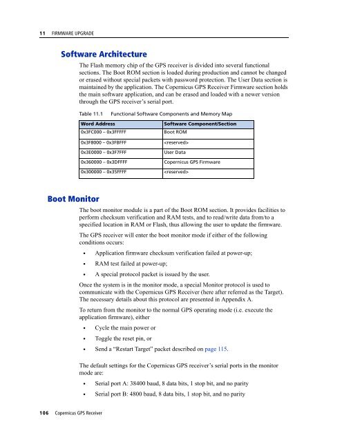
Software Architecture<br />
The Flash memory chip of the GPS receiver is divided into several functional<br />
sections. The Boot ROM section is loaded during production and cannot be changed<br />
or erased without special packets with password protection. The User Data section is<br />
maintained by the application. The Copernicus GPS Receiver Firmware section holds<br />
the main software application, and can be erased and loaded with a newer version<br />
through the GPS receiver’s serial port.<br />
Table 11.1<br />
Functional Software Components and Memory Map<br />
Word Address<br />
0x3FC000 – 0x3FFFFF<br />
0x3F8000 – 0x3FBFFF<br />
0x3E0000 – 0x3F7FFF<br />
0x360000 – 0x3DFFFF<br />
0x300000 – 0x35FFFF<br />
Software Component/Section<br />
Boot ROM<br />
<br />
User Data<br />
Copernicus GPS Firmware<br />
<br />
Boot Monitor<br />
The boot monitor module is a part of the Boot ROM section. It provides facilities to<br />
perform checksum verification and RAM tests, and to read/write data from/to a<br />
specified location in RAM or Flash, thus allowing the user to update the firmware.<br />
The GPS receiver will enter the boot monitor mode if either of the following<br />
conditions occurs:<br />
• Application firmware checksum verification failed at power-up;<br />
• RAM test failed at power-up;<br />
• A special protocol packet is issued by the user.<br />
Once the system is in the monitor mode, a special Monitor protocol is used to<br />
communicate with the Copernicus GPS Receiver (here after referred as the Target).<br />
The necessary details about this protocol are presented in Appendix A.<br />
To return from the monitor to the normal GPS operating mode (i.e. execute the<br />
application firmware), either<br />
• Cycle the main power or<br />
• Toggle the reset pin, or<br />
• Send a “Restart Target” packet described on page 115.<br />
The default settings for the Copernicus GPS receiver’s serial ports in the monitor<br />
mode are:<br />
• Serial port A: 38400 baud, 8 data bits, 1 stop bit, and no parity<br />
• Serial port B: 4800 baud, 8 data bits, 1 stop bit, and no parity<br />
106 Copernicus GPS Receiver