REFERENCE MANUAL - FTP Directory Listing - Trimble
REFERENCE MANUAL - FTP Directory Listing - Trimble
REFERENCE MANUAL - FTP Directory Listing - Trimble

Create successful ePaper yourself
Turn your PDF publications into a flip-book with our unique Google optimized e-Paper software.
INTERFACE CHARACTERISTICS 3<br />
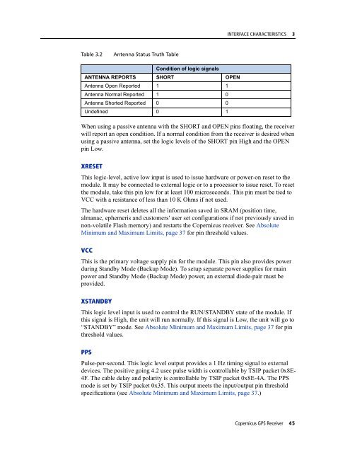
Table 3.2<br />
Antenna Status Truth Table<br />
Condition of logic signals<br />
ANTENNA REPORTS SHORT OPEN<br />
Antenna Open Reported 1 1<br />
Antenna Normal Reported 1 0<br />
Antenna Shorted Reported 0 0<br />
Undefined 0 1<br />
When using a passive antenna with the SHORT and OPEN pins floating, the receiver<br />
will report an open condition. If a normal condition from the receiver is desired when<br />
using a passive antenna, set the logic levels of the SHORT pin High and the OPEN<br />
pin Low.<br />
XRESET<br />
This logic-level, active low input is used to issue hardware or power-on reset to the<br />
module. It may be connected to external logic or to a processor to issue reset. To reset<br />
the module, take this pin low for at least 100 microseconds. This pin must be tied to<br />
VCC with a resistance of less than 10 K Ohms if not used.<br />
The hardware reset deletes all the information saved in SRAM (position time,<br />
almanac, ephemeris and customers' user set configurations if not previously saved in<br />
non-volatile Flash memory) and restarts the Copernicus receiver. See Absolute<br />
Minimum and Maximum Limits, page 37 for pin threshold values.<br />
VCC<br />
This is the primary voltage supply pin for the module. This pin also provides power<br />
during Standby Mode (Backup Mode). To setup separate power supplies for main<br />
power and Standby Mode (Backup Mode) power, an external diode-pair must be<br />
provided.<br />
XSTANDBY<br />
This logic level input is used to control the RUN/STANDBY state of the module. If<br />
this signal is High, the unit will run normally. If this signal is Low, the unit will go to<br />
“STANDBY” mode. See Absolute Minimum and Maximum Limits, page 37 for pin<br />
threshold values.<br />
PPS<br />
Pulse-per-second. This logic level output provides a 1 Hz timing signal to external<br />
devices. The positive going 4.2 usec pulse width is controllable by TSIP packet 0x8E-<br />
4F. The cable delay and polarity is controllable by TSIP packet 0x8E-4A. The PPS<br />
mode is set by TSIP packet 0x35. This output meets the input/output pin threshold<br />
specifications (see Absolute Minimum and Maximum Limits, page 37.)<br />
Copernicus GPS Receiver 45