REFERENCE MANUAL - FTP Directory Listing - Trimble
REFERENCE MANUAL - FTP Directory Listing - Trimble
REFERENCE MANUAL - FTP Directory Listing - Trimble

You also want an ePaper? Increase the reach of your titles
YUMPU automatically turns print PDFs into web optimized ePapers that Google loves.
A<br />
TRIMBLE STANDARD INTERFACE PROTOCOL (TSIP)<br />
Table A.44 (continued)<br />
Byte Item Type Definition / IDC -GPS-200<br />
139-146 n Double derived from delta_n<br />
147-154 r1me2 Double = sqrt(1.0-e 2 )<br />
155-162 OMEGA_n Double derived from OMEGA_0,<br />
OMEGADOT<br />
163-170 ODOT_n Double derived from OMEGADOT<br />
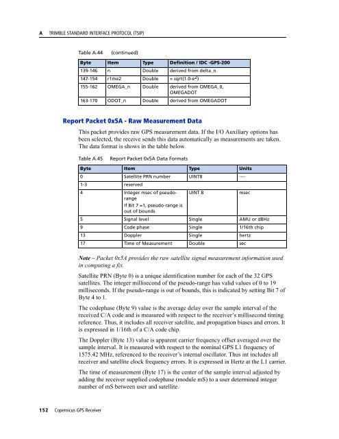
Report Packet 0x5A - Raw Measurement Data<br />
This packet provides raw GPS measurement data. If the I/O Auxiliary options has<br />
been selected, the receive sends this data automatically as measurements are taken.<br />
The data format is shows in the table below.<br />
Table A.45<br />
Report Packet 0x5A Data Formats<br />
Byte Item Type Units<br />
0 Satellite PRN number UINT8 ----<br />
1-3 reserved<br />
4 Integer msec of pseudorange<br />
If Bit 7 =1, pseudo-range is<br />
out of bounds<br />
UINT 8<br />
msec<br />
5 Signal level Single AMU or dBHz<br />
9 Code phase Single 1/16th chip<br />
13 Doppler Single hertz<br />
17 Time of Measurement Double sec<br />
Note – Packet 0x5A provides the raw satellite signal measurement information used<br />
in computing a fix.<br />
Satellite PRN (Byte 0) is a unique identification number for each of the 32 GPS<br />
satellites. The integer millisecond of the pseudo-range has valid values of 0 to 19<br />
milliseconds. If the pseudo-range is out of bounds, this is indicated by setting Bit 7 of<br />
Byte 4 to 1.<br />
The codephase (Byte 9) value is the average delay over the sample interval of the<br />
received C/A code and is measured with respect to the receiver’s millisecond timing<br />
reference. Thus, it includes all receiver satellite, and propagation biases and errors. It<br />
is expressed in 1/16th of a C/A code chip.<br />
The Doppler (Byte 13) value is apparent carrier frequency offset averaged over the<br />
sample interval. It is measured with respect to the nominal GPS L1 frequency of<br />
1575.42 MHz, referenced to the receiver’s internal oscillator. Thus int includes all<br />
receiver and satellite clock frequency errors. It is expressed in Hertz at the L1 carrier.<br />
The time of measurement (Byte 17) is the center of the sample interval adjusted by<br />
adding the receiver supplied codephase (module mS) to a user determined integer<br />
number of mS between user and satellite.<br />
152 Copernicus GPS Receiver