

Application and Optimisation of the Spatial Phase Shifting ...
Application and Optimisation of the Spatial Phase Shifting ...
Application and Optimisation of the Spatial Phase Shifting ...

You also want an ePaper? Increase the reach of your titles
YUMPU automatically turns print PDFs into web optimized ePapers that Google loves.
5.5 In-plane displacements 121<br />
possibility to compare TPS <strong>and</strong> SPS under <strong>the</strong> same experimental parameters. As soon as pure in-plane<br />
sensitivity is dem<strong>and</strong>ed, <strong>the</strong> interferometer assemblies are ra<strong>the</strong>r different, also from each o<strong>the</strong>r; we will<br />
discuss <strong>the</strong>se in <strong>the</strong> second part <strong>of</strong> this subsection.<br />
5.5.1 Mixed-sensitivity interferometer<br />
As mentioned earlier, <strong>the</strong> set-up <strong>of</strong> Fig. 5.1 need only be slightly changed to acquire a non-negligible inplane<br />
sensitivity component, which is shown in Fig. 5.7.<br />
y<br />
x<br />
M4<br />
S x<br />
z<br />
BS1<br />
MO1<br />
L1<br />
M1<br />
M3<br />
PZT<br />
M2<br />
HV<br />
amplifier<br />
BS2<br />
PF<br />
Waveform generator<br />
MO2<br />
PC<br />
frame memory<br />
trigger bit<br />
A<br />
∆x<br />
CCD<br />
L2<br />
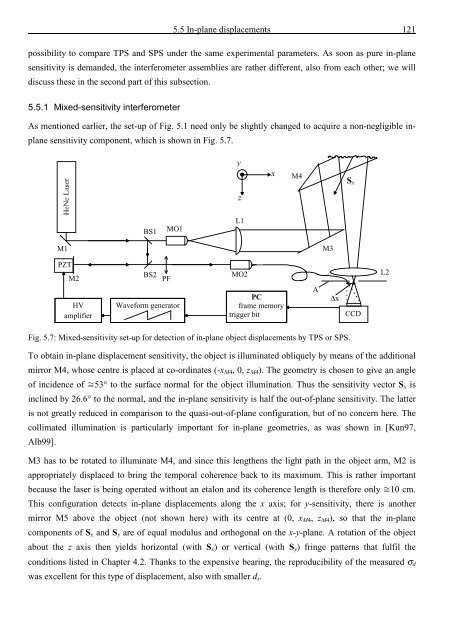
Fig. 5.7: Mixed-sensitivity set-up for detection <strong>of</strong> in-plane object displacements by TPS or SPS.<br />
To obtain in-plane displacement sensitivity, <strong>the</strong> object is illuminated obliquely by means <strong>of</strong> <strong>the</strong> additional<br />
mirror M4, whose centre is placed at co-ordinates (-x M4 , 0, z M4 ). The geometry is chosen to give an angle<br />
<strong>of</strong> incidence <strong>of</strong> 53° to <strong>the</strong> surface normal for <strong>the</strong> object illumination. Thus <strong>the</strong> sensitivity vector S x is<br />
inclined by 26.6° to <strong>the</strong> normal, <strong>and</strong> <strong>the</strong> in-plane sensitivity is half <strong>the</strong> out-<strong>of</strong>-plane sensitivity. The latter<br />
is not greatly reduced in comparison to <strong>the</strong> quasi-out-<strong>of</strong>-plane configuration, but <strong>of</strong> no concern here. The<br />
collimated illumination is particularly important for in-plane geometries, as was shown in [Kun97,<br />
Alb99].<br />
M3 has to be rotated to illuminate M4, <strong>and</strong> since this leng<strong>the</strong>ns <strong>the</strong> light path in <strong>the</strong> object arm, M2 is<br />
appropriately displaced to bring <strong>the</strong> temporal coherence back to its maximum. This is ra<strong>the</strong>r important<br />
because <strong>the</strong> laser is being operated without an etalon <strong>and</strong> its coherence length is <strong>the</strong>refore only 10 cm.<br />
This configuration detects in-plane displacements along <strong>the</strong> x axis; for y-sensitivity, <strong>the</strong>re is ano<strong>the</strong>r<br />
mirror M5 above <strong>the</strong> object (not shown here) with its centre at (0, x M4 , z M4 ), so that <strong>the</strong> in-plane<br />
components <strong>of</strong> S x <strong>and</strong> S y are <strong>of</strong> equal modulus <strong>and</strong> orthogonal on <strong>the</strong> x-y-plane. A rotation <strong>of</strong> <strong>the</strong> object<br />
about <strong>the</strong> z axis <strong>the</strong>n yields horizontal (with S x ) or vertical (with S y ) fringe patterns that fulfil <strong>the</strong><br />
conditions listed in Chapter 4.2. Thanks to <strong>the</strong> expensive bearing, <strong>the</strong> reproducibility <strong>of</strong> <strong>the</strong> measured σ d<br />
was excellent for this type <strong>of</strong> displacement, also with smaller d s .


![Skript zur Vorlesung [PDF; 40,0MB ;25.07.2005] - Institut für Physik](https://img.yumpu.com/28425341/1/184x260/skript-zur-vorlesung-pdf-400mb-25072005-institut-fa-1-4-r-physik.jpg?quality=85)


