

Application and Optimisation of the Spatial Phase Shifting ...
Application and Optimisation of the Spatial Phase Shifting ...
Application and Optimisation of the Spatial Phase Shifting ...

Create successful ePaper yourself
Turn your PDF publications into a flip-book with our unique Google optimized e-Paper software.
162 Improvements on SPS<br />
To obtain performance data for our approach, we use <strong>the</strong> σ d values from a simple out-<strong>of</strong>-plane tilt. The<br />
test object is a white painted metal plate that scatters with strong depolarisation (ρ = 0.78 ± 0.01). The<br />
light scattered <strong>of</strong>f <strong>the</strong> object is imaged with a lens L2 onto <strong>the</strong> target <strong>of</strong> <strong>the</strong> CCD camera, with 1024×768<br />
pixels. A polariser PF in front <strong>of</strong> <strong>the</strong> camera target selects ei<strong>the</strong>r <strong>the</strong> vertical or horizontal SOP <strong>of</strong> <strong>the</strong><br />
scattered light. The measured correlation coefficient for <strong>the</strong> corresponding speckle fields S vi (x,y) <strong>and</strong><br />
S hi (x,y) is c = 0.02 ± 0.005 which is in acceptable agreement with <strong>the</strong> value <strong>of</strong> c = 0.03 ± 0.003 expected<br />
for <strong>the</strong> measured depolarisation coefficient. Since S v /S h 0.78, <strong>the</strong> plane <strong>of</strong> polarisation <strong>of</strong> <strong>the</strong><br />
reference wave is set to 48° instead <strong>of</strong> 45° by <strong>the</strong> POC to obtain P vb (x,y)P hb (x,y), this is, we intend to<br />
replace some 50% <strong>of</strong> ϕ O,vi (x,y) (ϕ O,vf (x,y)) by entries from ϕ O,hi (x,y) (ϕ O,hf (x,y)), whereby <strong>the</strong> best<br />
utilisation <strong>of</strong> both speckle patterns is assured.<br />
The reference wave's fibre end is placed in <strong>the</strong> aperture plane A <strong>of</strong> <strong>the</strong> imaging system <strong>and</strong> positioned to<br />
yield α x = 120°/column on <strong>the</strong> CCD sensor.<br />
The phase stabilisation works as follows: part <strong>of</strong> <strong>the</strong> object light is reflected by <strong>the</strong> small mirror M1<br />
mounted on <strong>the</strong> object. It passes through <strong>the</strong> lens L2 <strong>and</strong> is <strong>the</strong>n reflected by ano<strong>the</strong>r small mirror M2,<br />
close beside <strong>the</strong> CCD chip, towards <strong>the</strong> plane S. On <strong>the</strong> opposite side <strong>of</strong> <strong>the</strong> CCD sensor, a small<br />
beamsplitter BS reflects a part <strong>of</strong> <strong>the</strong> reference wave towards S. By proper adjustment <strong>of</strong> M1, M2 <strong>and</strong> BS,<br />
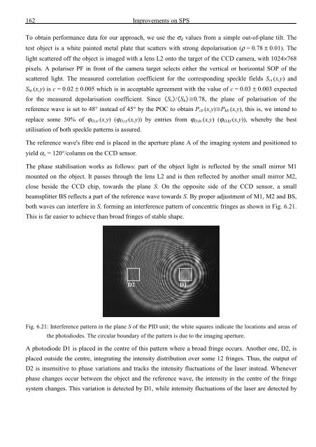
both waves can interfere in S, forming an interference pattern <strong>of</strong> concentric fringes as shown in Fig. 6.21.<br />
This is far easier to achieve than broad fringes <strong>of</strong> stable shape.<br />
D2<br />
D1<br />
Fig. 6.21: Interference pattern in <strong>the</strong> plane S <strong>of</strong> <strong>the</strong> PID unit; <strong>the</strong> white squares indicate <strong>the</strong> locations <strong>and</strong> areas <strong>of</strong><br />
<strong>the</strong> photodiodes. The circular boundary <strong>of</strong> <strong>the</strong> pattern is due to <strong>the</strong> imaging aperture.<br />
A photodiode D1 is placed in <strong>the</strong> centre <strong>of</strong> this pattern where a broad fringe occurs. Ano<strong>the</strong>r one, D2, is<br />
placed outside <strong>the</strong> centre, integrating <strong>the</strong> intensity distribution over some 12 fringes. Thus, <strong>the</strong> output <strong>of</strong><br />
D2 is insensitive to phase variations <strong>and</strong> tracks <strong>the</strong> intensity fluctuations <strong>of</strong> <strong>the</strong> laser instead. Whenever<br />
phase changes occur between <strong>the</strong> object <strong>and</strong> <strong>the</strong> reference wave, <strong>the</strong> intensity in <strong>the</strong> centre <strong>of</strong> <strong>the</strong> fringe<br />
system changes. This variation is detected by D1, while intensity fluctuations <strong>of</strong> <strong>the</strong> laser are detected by


![Skript zur Vorlesung [PDF; 40,0MB ;25.07.2005] - Institut für Physik](https://img.yumpu.com/28425341/1/184x260/skript-zur-vorlesung-pdf-400mb-25072005-institut-fa-1-4-r-physik.jpg?quality=85)


