

Application and Optimisation of the Spatial Phase Shifting ...
Application and Optimisation of the Spatial Phase Shifting ...
Application and Optimisation of the Spatial Phase Shifting ...

You also want an ePaper? Increase the reach of your titles
YUMPU automatically turns print PDFs into web optimized ePapers that Google loves.
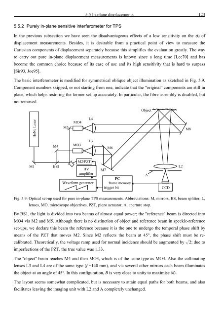
5.5 In-plane displacements 123<br />
5.5.2 Purely in-plane sensitive interferometer for TPS<br />
In <strong>the</strong> previous subsection we have seen <strong>the</strong> disadvantageous effects <strong>of</strong> a low sensitivity on <strong>the</strong> σ d <strong>of</strong><br />
displacement measurements. Besides, it is desirable from a practical point <strong>of</strong> view to measure <strong>the</strong><br />
Cartesian components <strong>of</strong> displacement separately because this simplifies <strong>the</strong> evaluation greatly. The way<br />
to carry out pure in-plane displacement measurements is known since a long time [Lee70] <strong>and</strong> has<br />
become <strong>the</strong> common choice because <strong>of</strong> its ease <strong>of</strong> use <strong>and</strong> its high sensitivity that is hard to surpass<br />
[Sir93, Joe95].<br />
The basic interferometer is modified for symmetrical oblique object illumination as sketched in Fig. 5.9.<br />
Component numbers skipped, or not starting from one, indicate that <strong>the</strong> "original" components are still in<br />
place, which helps restoring <strong>the</strong> former set-up accurately. In particular, <strong>the</strong> fibre assembly is disabled, but<br />
not removed.<br />
Object<br />
M5<br />
MO4<br />
L4<br />
M8<br />
M4<br />
MO3<br />
L3<br />
M6<br />
M1<br />
BS1<br />
M2/PZT<br />
HV<br />
amplifier<br />
Waveform generator<br />
M7<br />
PC<br />
frame memory<br />
trigger bit<br />
A<br />
CCD<br />
L2<br />
Fig. 5.9: Optical set-up used for pure in-plane TPS measurements. Abbreviations: M, mirrors, BS, beam splitter, L,<br />
lenses, MO, microscope objectives, PZT, piezo actuator, A, aperture stop.<br />
By BS1, <strong>the</strong> light is divided into two beams <strong>of</strong> almost equal power; <strong>the</strong> "reference" beam is directed into<br />
MO4 via M2 <strong>and</strong> M5. Although <strong>the</strong>re is no distinction <strong>of</strong> object <strong>and</strong> reference beam in speckle-reference<br />
set-ups, we declare this beam <strong>the</strong> reference because it is <strong>the</strong> one to undergo <strong>the</strong> temporal phase shift by<br />
means <strong>of</strong> <strong>the</strong> PZT that moves M2. Since M2 reflects <strong>the</strong> beam at 45°, <strong>the</strong> phase shift must be recalibrated.<br />
Theoretically, <strong>the</strong> voltage ramp used for normal incidence should be augmented by L2; due to<br />
imperfections <strong>of</strong> <strong>the</strong> PZT, <strong>the</strong> true value was 1.33.<br />
The "object" beam reaches M4 <strong>and</strong> <strong>the</strong>n MO3, which is <strong>of</strong> <strong>the</strong> same type as MO4. Also <strong>the</strong> collimating<br />
lenses L3 <strong>and</strong> L4 are <strong>of</strong> <strong>the</strong> same type (f =140 mm), <strong>and</strong> via several o<strong>the</strong>r mirrors each beam illuminates<br />
<strong>the</strong> object at an angle <strong>of</strong> 45°. In this configuration, B is very close to unity to maximise M I .<br />
The layout seems somewhat complicated, but is necessary to attain equal paths for both beams, <strong>and</strong> also<br />
facilitates leaving <strong>the</strong> imaging unit with L2 <strong>and</strong> A completely unchanged.


![Skript zur Vorlesung [PDF; 40,0MB ;25.07.2005] - Institut für Physik](https://img.yumpu.com/28425341/1/184x260/skript-zur-vorlesung-pdf-400mb-25072005-institut-fa-1-4-r-physik.jpg?quality=85)


