

Application and Optimisation of the Spatial Phase Shifting ...
Application and Optimisation of the Spatial Phase Shifting ...
Application and Optimisation of the Spatial Phase Shifting ...

Create successful ePaper yourself
Turn your PDF publications into a flip-book with our unique Google optimized e-Paper software.
5.5 In-plane displacements 127<br />
<strong>the</strong> first one on <strong>the</strong> abscissa. Never<strong>the</strong>less, <strong>the</strong> plots are scaled as in Fig. 5.10 to make <strong>the</strong> visual<br />
comparison easier. Because we have a symmetrical 45° set-up also here, <strong>the</strong> conversion factors <strong>and</strong> σ d,max<br />
are <strong>the</strong> same as in 5.5.2.<br />
0.20<br />
0.18<br />
0.16<br />
0.14<br />
0.12<br />
σ d /λ<br />
0.10<br />
0.08<br />
0.06<br />
0.04<br />
0.02<br />
0.00<br />
0 5 10 15<br />
20 30 40 50<br />
60 70 90 100<br />
0 2 4 6 8 d s /d p 10<br />
N y<br />
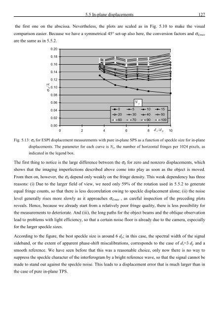
Fig. 5.13: σ d for ESPI displacement measurements with pure in-plane SPS as a function <strong>of</strong> speckle size for in-plane<br />
displacements. The parameter for each curve is N y , <strong>the</strong> number <strong>of</strong> horizontal fringes per 1024 pixels, as<br />
indicated in <strong>the</strong> legend box.<br />
The first thing to notice is <strong>the</strong> large difference between <strong>the</strong> σ d for zero <strong>and</strong> nonzero displacements, which<br />
shows that <strong>the</strong> imaging imperfections described above come into play as soon as <strong>the</strong> object is moved.<br />
From <strong>the</strong>n on, however, <strong>the</strong> σ d depend only weakly on <strong>the</strong> fringe density. This weak dependency has three<br />
reasons: (i) Due to <strong>the</strong> larger field <strong>of</strong> view, we need only 59% <strong>of</strong> <strong>the</strong> rotation used in 5.5.2 to generate<br />
equal fringe counts, so that <strong>the</strong>re is less decorrelation owing to speckle displacement alone; (ii) <strong>the</strong> noise<br />
level generally rises more slowly as it approaches σ d,max , as careful inspection <strong>of</strong> <strong>the</strong> preceding plots<br />
reveals. Hence, because we already start from a relatively poor fringe quality, <strong>the</strong>re is less possibility for<br />
<strong>the</strong> measurements to deteriorate. And (iii), <strong>the</strong> long paths for <strong>the</strong> object beams <strong>and</strong> <strong>the</strong> oblique observation<br />
lead to problems with light efficiency, so that a certain noise floor is already due to <strong>the</strong> camera, especially<br />
for <strong>the</strong> larger speckle sizes.<br />
According to <strong>the</strong> figure, <strong>the</strong> best speckle size is around 6 d p ; in this case, <strong>the</strong> spectral width <strong>of</strong> <strong>the</strong> signal<br />
sideb<strong>and</strong>, or <strong>the</strong> extent <strong>of</strong> apparent phase-shift miscalibrations, corresponds to <strong>the</strong> case <strong>of</strong> d s =3 d p <strong>and</strong> a<br />
smooth reference. We have seen before that this was a reasonable choice, only now <strong>the</strong>re is no way to<br />
suppress <strong>the</strong> speckle character <strong>of</strong> <strong>the</strong> interferogram by a bright reference wave, so that <strong>the</strong> signal cannot be<br />
made to st<strong>and</strong> out against <strong>the</strong> speckle noise. This leads to a displacement error that is much larger than in<br />
<strong>the</strong> case <strong>of</strong> pure in-plane TPS.


![Skript zur Vorlesung [PDF; 40,0MB ;25.07.2005] - Institut für Physik](https://img.yumpu.com/28425341/1/184x260/skript-zur-vorlesung-pdf-400mb-25072005-institut-fa-1-4-r-physik.jpg?quality=85)


