

Application and Optimisation of the Spatial Phase Shifting ...
Application and Optimisation of the Spatial Phase Shifting ...
Application and Optimisation of the Spatial Phase Shifting ...

Create successful ePaper yourself
Turn your PDF publications into a flip-book with our unique Google optimized e-Paper software.
6.6 Use <strong>of</strong> depolarisation to eliminate invalid pixels 161<br />
for <strong>the</strong> initial object state. By this approach, two merged (index m) phase maps ϕ O,mi (x,y) <strong>and</strong> ϕ O,mf (x,y)<br />
are generated, whose correlation is maintained with respect to <strong>the</strong> pixel replacement.<br />
Since <strong>the</strong> phase <strong>of</strong>fsets N 0v <strong>and</strong> N 0h (cf. Chapter 4.2) should be <strong>the</strong> same for both sawtooth images to<br />
merge, <strong>the</strong>y should be kept constant during <strong>the</strong> recording <strong>of</strong> <strong>the</strong> two interferogram pairs I vi , I hi <strong>and</strong> I vf , I hf .<br />
In principle, it is possible to correct a phase <strong>of</strong>fset a posteriori <strong>and</strong> make both fringe systems fit toge<strong>the</strong>r<br />
by subtracting a constant phase from one <strong>of</strong> <strong>the</strong> sawtooth images; but <strong>the</strong> error fringe pr<strong>of</strong>iles (cf. Fig.<br />
3.39) are related to <strong>the</strong> actual physical phase <strong>of</strong>fset, so that such a "makeshift" will produce artefacts <strong>and</strong><br />
lead to unsatisfactory results. Therefore, a phase stabilisation system to compensate phase fluctuations by,<br />
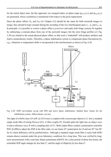
e.g., vibrations or temperature drifts is incorporated in <strong>the</strong> interferometer as shown in Fig. 6.20.<br />
Object<br />
M1<br />
L1<br />
POC<br />
FC<br />
O<br />
R<br />
POC<br />
PZ<br />
HV<br />
M2<br />
PF<br />
L2<br />
A<br />
S<br />
BS<br />
D1<br />
D2<br />
PID<br />
CCD<br />
Fig. 6.20: ESPI out-<strong>of</strong>-plane set-up with SPS <strong>and</strong> active phase stabilisation. Dashed lines: beams for <strong>the</strong><br />
stabilisation system. Abbreviations: see text.<br />
The light <strong>of</strong> a HeNe laser (25 mW @ 632.8 nm) is coupled with a microscope objective L1 into a st<strong>and</strong>ard<br />
single mode fibre (Corning Flexcor 633). A fibre coupler FC (Gould) splits <strong>the</strong> light into an object wave<br />
O <strong>and</strong> a reference wave R with a coupling ratio <strong>of</strong> 9:1. Both output fibres contain a polarisation controller<br />
POC [Lef80] to adjust <strong>the</strong> SOP at <strong>the</strong> fibre ends; we use linear 45° polarisation for O <strong>and</strong> not 45° but 48°<br />
for R, which difference will be justified below. Although a st<strong>and</strong>ard single mode fibre is used, both SOPs<br />
remain almost constant under <strong>the</strong> given laboratory conditions for a long time. This was verified by longterm<br />
measurements with a real-time Stokes polarimeter [Dir97]: for a time period <strong>of</strong> about four hours, <strong>the</strong><br />
azimuthal SOP angle changes by less than 2°, <strong>and</strong> <strong>the</strong> angle <strong>of</strong> ellipticity by less than 4°.


![Skript zur Vorlesung [PDF; 40,0MB ;25.07.2005] - Institut für Physik](https://img.yumpu.com/28425341/1/184x260/skript-zur-vorlesung-pdf-400mb-25072005-institut-fa-1-4-r-physik.jpg?quality=85)


