Application and Optimisation of the Spatial Phase Shifting ...
Application and Optimisation of the Spatial Phase Shifting ...
Application and Optimisation of the Spatial Phase Shifting ...
Create successful ePaper yourself
Turn your PDF publications into a flip-book with our unique Google optimized e-Paper software.
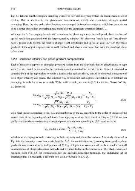
144 Improvements on SPS<br />
Fig. 6.7 tells us that <strong>the</strong> complete sampling window is now definitely larger than <strong>the</strong> mean speckle size <strong>of</strong><br />
d s =3 d p . But in addition to <strong>the</strong> phase-error compensation, (3.56) also constitutes stronger spatial<br />
averaging. Here, <strong>the</strong> sine <strong>and</strong> cosine functions are averaged before phase retrieval, which has been shown<br />
to be a better choice than averaging phase maps after <strong>the</strong> arctangent operation [Hun97].<br />
Although <strong>the</strong> 3+3 averaging formula still calculates <strong>the</strong> phase separately for each pixel, <strong>the</strong>re is a loss <strong>of</strong><br />
spatial resolution associated with <strong>the</strong> larger sampling window. But since our "resolution cell" has already<br />
been 3 pixels wide before, <strong>the</strong> relative change is not significant; <strong>and</strong> up to (at least) N x =100, <strong>the</strong> phase<br />
gradient <strong>of</strong> <strong>the</strong> object displacement is well resolved <strong>and</strong> shows less noise than with <strong>the</strong> st<strong>and</strong>ard phase<br />
calculation.<br />
6.2.3 Combined intensity <strong>and</strong> phase gradient compensation<br />
Each <strong>of</strong> <strong>the</strong> error-suppression strategies proposed suffers from <strong>the</strong> drawback that its effectiveness to cope<br />
with I x or ϕ O,x could be reduced by <strong>the</strong> fluctuations not accounted for, i.e. ϕ O,x or I x . Hence it is natural to<br />
combine both <strong>of</strong> <strong>the</strong> approaches to obtain a formula that reduces <strong>the</strong> σ d caused by <strong>the</strong> speckle structure <strong>of</strong><br />
both object intensity <strong>and</strong> phase. The simplest way to construct such a phase calculation is to establish an<br />
averaging formula for terms as in (6.4). With α=90°/sample, we rewrite (6.5) for <strong>the</strong> two "boxes" <strong>of</strong> Fig.<br />
6.7 [Bur98a]:<br />
tan ϕ<br />
tan ϕ<br />
O0<br />
O1<br />
=<br />
=<br />
O0 ( D1 − D−1)<br />
O ( D − D ) − O ( D − D ) : =<br />
1 −1 0 −1 0 1<br />
O1 ( D2 − D0<br />
)<br />
O ( D D ) O ( D D ) : =<br />
− − − K<br />
2 0 1 0 1 2<br />
K2<br />
K − K<br />
3 1<br />
K5<br />
− K<br />
6 4<br />
, (6.7)<br />
with pixel indices according to Fig. 6.7, <strong>and</strong> numbering <strong>of</strong> <strong>the</strong> K n according to <strong>the</strong> order <strong>of</strong> indices <strong>of</strong> <strong>the</strong><br />
square roots at <strong>the</strong> beginning <strong>of</strong> each term. Now applying what we have learnt in Chapter 3.2.2.4, we can<br />
easily compose <strong>the</strong>se two intensity-corrected phase calculations according to (3.55) <strong>and</strong> arrive at<br />
ϕ<br />
O<br />
mod π = arctan<br />
K2 + K4 − K6<br />
− K + K + K<br />
1 3 5<br />
, (6.8)<br />
which is an averaging formula correcting for both intensity <strong>and</strong> phase fluctuations. As already indicated in<br />
Fig. 6.6, <strong>the</strong> intensity correction works best for B=3; <strong>the</strong> contribution to σ d coming from speckle phase<br />
gradients was assumed to be independent <strong>of</strong> B. Fig. 6.9 gives an overview <strong>of</strong> <strong>the</strong> best results from all<br />
combinations <strong>of</strong> phase-calculation methods <strong>and</strong> B values tested in this subsection. The black curves are<br />
repeated from Fig. 6.8 for comparison; for <strong>the</strong> intensity-correcting formulae, <strong>the</strong> underlying set <strong>of</strong><br />
interferograms is necessarily a different one, with B=3, but also d s =3 d p .





![Skript zur Vorlesung [PDF; 40,0MB ;25.07.2005] - Institut für Physik](https://img.yumpu.com/28425341/1/184x260/skript-zur-vorlesung-pdf-400mb-25072005-institut-fa-1-4-r-physik.jpg?quality=85)
