

Application and Optimisation of the Spatial Phase Shifting ...
Application and Optimisation of the Spatial Phase Shifting ...
Application and Optimisation of the Spatial Phase Shifting ...

Create successful ePaper yourself
Turn your PDF publications into a flip-book with our unique Google optimized e-Paper software.
80 Electronic or Digital Speckle Pattern Interferometry<br />
<strong>and</strong> all have <strong>the</strong> same I b <strong>and</strong> M I , which is difficult to achieve [Kuj91a, Het00]. If parts <strong>of</strong> one <strong>and</strong> <strong>the</strong> same<br />
sensor are used for <strong>the</strong> sub-images, resolution is lost; if several full-chip images are taken, <strong>the</strong>y will have<br />
to share <strong>the</strong> light energy available. High expense on <strong>the</strong> components, great adjustment effort <strong>and</strong> high<br />
sensitivity to misalignment are to be expected when working with set-ups <strong>of</strong> this type.<br />
The phase-ramping or bucket method <strong>of</strong> SPS works with one detector, on which a dense additional fringe<br />
pattern is generated to function as a so-called spatial phase bias or, in <strong>the</strong> Fourier terminology, carrier<br />
frequency. The – low-frequency – signal <strong>of</strong> interest distorts <strong>the</strong> carrier pattern <strong>and</strong> can be retrieved from it<br />
by a number <strong>of</strong> methods [Wom84]. This approach has first been implemented with vertical carrier fringes<br />
in [Ich72, Mer83] as analogue real-time processing <strong>of</strong> TV line signals. (Note here that only SPS lends<br />
itself to this technique: TPS requires digital processing since separate TV frames are involved.) The first<br />
studies were soon followed by digital implementations [Toy84, Toy86, Sho90, Fre90b,c, Küch90,<br />
Küch91, Kuj91b], allowing for arbitrary directions <strong>of</strong> <strong>the</strong> carrier fringes. Also, it was demonstrated in<br />
[Tak82] that <strong>the</strong> signal can conveniently be retrieved in <strong>the</strong> frequency plane by a Fourier-transform<br />
method; we defer details to Chapter 6.5. O<strong>the</strong>r methods to retrieve phase from images with a spatial<br />
carrier are <strong>the</strong> phase-locked-loop method [Ser93] <strong>and</strong> <strong>the</strong> frequency demodulation technique [Ara96].<br />
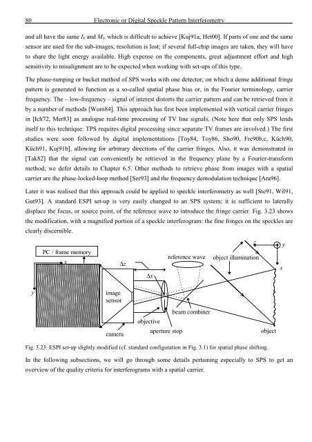
Later it was realised that this approach could be applied to speckle interferometry as well [Ste91, Wil91,<br />
Gut93]. A st<strong>and</strong>ard ESPI set-up is very easily changed to an SPS system; it is sufficient to laterally<br />
displace <strong>the</strong> focus, or source point, <strong>of</strong> <strong>the</strong> reference wave to introduce <strong>the</strong> fringe carrier. Fig. 3.23 shows<br />
<strong>the</strong> modification, with a magnified portion <strong>of</strong> a speckle interferogram: <strong>the</strong> fine fringes on <strong>the</strong> speckles are<br />
clearly discernible.<br />
z y<br />
PC / frame memory<br />
reference wave object illumination<br />
x<br />
∆z<br />
x<br />
∆x<br />
y<br />
image<br />
sensor<br />
camera<br />
objective<br />
aperture stop<br />
beam combiner<br />
object<br />
Fig. 3.23: ESPI set-up slightly modified (cf. st<strong>and</strong>ard configuration in Fig. 3.1) for spatial phase shifting.<br />
In <strong>the</strong> following subsections, we will go through some details pertaining especially to SPS to get an<br />
overview <strong>of</strong> <strong>the</strong> quality criteria for interferograms with a spatial carrier.


![Skript zur Vorlesung [PDF; 40,0MB ;25.07.2005] - Institut für Physik](https://img.yumpu.com/28425341/1/184x260/skript-zur-vorlesung-pdf-400mb-25072005-institut-fa-1-4-r-physik.jpg?quality=85)


