

Application and Optimisation of the Spatial Phase Shifting ...
Application and Optimisation of the Spatial Phase Shifting ...
Application and Optimisation of the Spatial Phase Shifting ...

You also want an ePaper? Increase the reach of your titles
YUMPU automatically turns print PDFs into web optimized ePapers that Google loves.
5.5 In-plane displacements 125<br />
Object<br />
M3<br />
M4<br />
M1<br />
MO3<br />
L4<br />
M2<br />
MP<br />
∆x<br />
Aperture shape<br />
M5<br />
DA<br />
L3<br />
M6<br />
∆x<br />
D<br />
DA<br />
PC<br />
frame memory<br />
CCD<br />
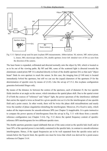
Fig. 5.11: Optical set-up used for pure in-plane SPS measurements. Abbreviations: M, mirrors, MP, mirror prism,<br />
L, lenses, MO, microscope objective, DA, double aperture; lower left: detailed view <strong>of</strong> DA as seen from<br />
<strong>the</strong> direction <strong>of</strong> <strong>the</strong> camera.<br />
The laser beam is exp<strong>and</strong>ed, collimated <strong>and</strong> directed normally onto <strong>the</strong> object by M4, which is located so<br />
as to be out <strong>of</strong> <strong>the</strong> viewing paths. By M5 <strong>and</strong> M6, some <strong>of</strong> <strong>the</strong> scattered light is directed towards <strong>the</strong><br />
aluminium coated prism MP. It is attached directly in front <strong>of</strong> <strong>the</strong> double aperture DA so that each "object<br />
beam" finds its own aperture to reach <strong>the</strong> sensor. In this case, <strong>the</strong> imaging lens (f=140 mm) is located<br />
immediately behind <strong>the</strong> apertures, but still we can use <strong>the</strong> (equal) diameters <strong>of</strong> <strong>the</strong> apertures D for <strong>the</strong><br />
determination <strong>of</strong> speckle sizes by means <strong>of</strong> (2.43). Like <strong>the</strong> set-up <strong>of</strong> 5.5.2, this in-plane configuration<br />
generates horizontal fringes only.<br />
By means <strong>of</strong> <strong>the</strong> distance ∆x between <strong>the</strong> centres <strong>of</strong> <strong>the</strong> apertures, each <strong>of</strong> diameter D, <strong>the</strong> two speckle<br />
fields interfere at an angle on <strong>the</strong> sensor, which introduces <strong>the</strong> spatial phase shift. Due to <strong>the</strong> spatial extent<br />
D <strong>of</strong> both <strong>the</strong> sources <strong>of</strong> "reference" <strong>and</strong> "object" light, <strong>the</strong> power spectrum <strong>of</strong> <strong>the</strong> interference sideb<strong>and</strong><br />
that carries <strong>the</strong> signal is twice as broad for a given speckle size as it is for <strong>the</strong> interferogram <strong>of</strong> one speckle<br />
field <strong>and</strong> a point source. In o<strong>the</strong>r words, <strong>the</strong>re will be twice <strong>the</strong> phase shift miscalibrations <strong>and</strong> nearly<br />
twice <strong>the</strong> number <strong>of</strong> phase singularities disturbing <strong>the</strong> interferogram. Moreover, B is fixed to unity, which<br />
makes all <strong>the</strong> improvements for smooth-reference SPS (see Chapter 5) inapplicable. It is quite instructive<br />
to compare <strong>the</strong> power spectra <strong>of</strong> interferograms from <strong>the</strong> set-up in Fig. 5.11 with those from a smoothreference<br />
configuration (see Chapter 3.4.4). Fig. 5.12 shows <strong>the</strong> spatial frequency content <strong>of</strong> specklereference<br />
SPS interferograms for two different speckle sizes.<br />
The double aperture generates signal sideb<strong>and</strong>s that are <strong>of</strong> <strong>the</strong> same extent as <strong>the</strong> speckle halo itself, <strong>and</strong> at<br />
least 50% <strong>of</strong> <strong>the</strong> spectral power is inevitably contained in <strong>the</strong> speckle halo, in contrast to smooth-reference<br />
interferograms. Hence, if <strong>the</strong> signal frequencies are to be well separated from <strong>the</strong> speckle noise <strong>and</strong> to<br />
remain below <strong>the</strong> Nyqvist limit, <strong>the</strong> speckle size must be twice that which was derived for a point-source<br />
reference in Chapter 3.4.4.


![Skript zur Vorlesung [PDF; 40,0MB ;25.07.2005] - Institut für Physik](https://img.yumpu.com/28425341/1/184x260/skript-zur-vorlesung-pdf-400mb-25072005-institut-fa-1-4-r-physik.jpg?quality=85)


