

This section is available on request - MAN Diesel & Turbo
This section is available on request - MAN Diesel & Turbo
This section is available on request - MAN Diesel & Turbo

Create successful ePaper yourself
Turn your PDF publications into a flip-book with our unique Google optimized e-Paper software.
<strong>MAN</strong> B&W 17.05<br />
As the deflecti<strong>on</strong> shape for the H�type <str<strong>on</strong>g>is</str<strong>on</strong>g> equal<br />
for each cylinder the N th order H�type guide force<br />
moment for an N�cylinder engine with regular firing<br />
order <str<strong>on</strong>g>is</str<strong>on</strong>g>:<br />
N x M H(<strong>on</strong>e cylinder)<br />
For modelling purposes the size of the forces in<br />
the force couple <str<strong>on</strong>g>is</str<strong>on</strong>g>:<br />
Force = M H /L [kN]<br />
where L <str<strong>on</strong>g>is</str<strong>on</strong>g> the d<str<strong>on</strong>g>is</str<strong>on</strong>g>tance between crankshaft level<br />
and the middle positi<strong>on</strong> of the crosshead guide<br />
(i.e. the length of the c<strong>on</strong>necting rod.)<br />
As the interacti<strong>on</strong> between engine and hull <str<strong>on</strong>g>is</str<strong>on</strong>g> at<br />
the engine seating and the top bracing positi<strong>on</strong>s,<br />
th<str<strong>on</strong>g>is</str<strong>on</strong>g> force couple may alternatively be applied in<br />
those positi<strong>on</strong>s with a vertical d<str<strong>on</strong>g>is</str<strong>on</strong>g>tance of (L Z ).<br />
Then the force can be calculated as:<br />
Force Z = M H /L Z [kN]<br />
Any other vertical d<str<strong>on</strong>g>is</str<strong>on</strong>g>tance may be applied, so as<br />
to accomodate the actual hull (FEM) model.<br />
The force couple may be d<str<strong>on</strong>g>is</str<strong>on</strong>g>tributed at any<br />
number of points in the l<strong>on</strong>gitudinal directi<strong>on</strong>. A<br />
reas<strong>on</strong>able way of dividing the couple <str<strong>on</strong>g>is</str<strong>on</strong>g> by the<br />
number of top bracing and then applying the forces<br />
at those points.<br />
Force Z, <strong>on</strong>e point = Force Z, total /N top bracing, total [kN]<br />
X�type Guide Force Moment (M X )<br />
The X�type guide force moment <str<strong>on</strong>g>is</str<strong>on</strong>g> calculated<br />
based <strong>on</strong> the same force couple as described<br />
above. However as the deflecti<strong>on</strong> shape <str<strong>on</strong>g>is</str<strong>on</strong>g> tw<str<strong>on</strong>g>is</str<strong>on</strong>g>ting<br />
the engine each cylinder unit does not c<strong>on</strong>tribute<br />
with an equal amount. The centre units do not<br />
c<strong>on</strong>tribute very much whereas the units at each<br />
end c<strong>on</strong>tributes much.<br />
A so�called ‘Bi�moment’ can be calculated (Fig.<br />
17.05.01):<br />
‘Bi�moment’ = Σ [force�couple(cyl.X) x d<str<strong>on</strong>g>is</str<strong>on</strong>g>tX]<br />
in kNm 2<br />
Page of<br />
The X�type guide force moment <str<strong>on</strong>g>is</str<strong>on</strong>g> then defined<br />
as:<br />
M X = ‘Bi�Moment’/L kNm<br />
For modelling purpose the size of the four (4) forces<br />
can be calculated:<br />
Force = M X /L X [kN]<br />
where:<br />
L X <str<strong>on</strong>g>is</str<strong>on</strong>g> the horiz<strong>on</strong>tal length between ‘force points’<br />
Similar to the situati<strong>on</strong> for the H�type guide force<br />
moment, the forces may be applied in positi<strong>on</strong>s<br />
suitable for the FEM model of the hull. Thus the<br />
forces may be referred to another vertical level L Z<br />
above crankshaft centre line. These forces can be<br />
calculated as follows:<br />
Force = Z, <strong>on</strong>e point M _____ x L x<br />
L x L [kN]<br />
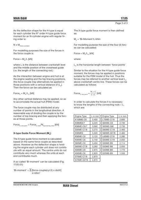
In order to calculate the forces it <str<strong>on</strong>g>is</str<strong>on</strong>g> necessary<br />
to know the lengths of the c<strong>on</strong>necting rods = L,<br />
which are:<br />
Engine Type L in mm<br />
K108ME�C6 ,400<br />
K98ME6/7 ,220<br />
K98ME�C6/7 ,090<br />
S90ME�C7/8 ,270<br />
K90ME9 , 20<br />
K90ME-C9 ,120<br />
K90ME�C6 ,159<br />
S80ME�C9 ,450<br />
S80ME�C7/8 ,280<br />
K80ME�C9 2,975<br />
K80ME�C6 2,920<br />
S70ME-C7/8 2,870<br />
S70ME�GI7/8 2,870<br />
Engine Type L in mm<br />
L70ME�C7/8 2,660<br />
S65ME�C8 2,7 0<br />
S65ME�GI8 2,7 0<br />
S60ME�C7/8 2,460<br />
S60ME�GI7/8 2,460<br />
L60ME�C7/8 2,280<br />
S50ME�C7/8 2,050<br />
S50ME-B9 2,114<br />
S50ME-B8 2,050<br />
S40ME-B9 1,770<br />
S 5ME-B9 1,550<br />
<strong>MAN</strong> B&W ME/ME-B/ME�C/ME�GI engines 198 45 17�0.5<br />
<strong>MAN</strong> <strong>Diesel</strong>


