Carbon Nanotube Reinforced Composites: Metal and Ceramic ...
Carbon Nanotube Reinforced Composites: Metal and Ceramic ...
Carbon Nanotube Reinforced Composites: Metal and Ceramic ...
You also want an ePaper? Increase the reach of your titles
YUMPU automatically turns print PDFs into web optimized ePapers that Google loves.
104j 4 Mechanical Characteristics of <strong>Carbon</strong> <strong>Nanotube</strong>–<strong>Metal</strong> Nanocomposites<br />
Experimental results of tensile measurements are then compared or correlated with<br />
such theoretical models.<br />
The micromechanical models for discontinuously fiber-reinforced composites are<br />
briefly discussed here. The mechanical properties of such composites are mainly<br />
controlled by the stress transfer between the reinforcing fibers <strong>and</strong> the metal matrix at<br />
the interface. The strengthening mechanism through load transfer from the matrix to<br />
the reinforcement can be estimated from the shear-lag model. Cox originally<br />
proposed this approach where discontinuous fibers were embedded in an elastic<br />
matrix with a perfectly bonded interface <strong>and</strong> loaded in tension along the fiber<br />
direction [6]. Further, load transfer depends on the interfacial shear stress between<br />
the fiber <strong>and</strong> the matrix. The Cox model incorporates the aspect ratio (S ¼ l/d where l<br />
is the fiber length <strong>and</strong> d is the fiber diameter) of the reinforcement into the rule of<br />
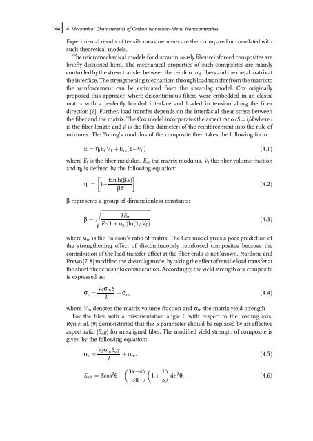
mixtures. The Young s modulus of the composite then takes the following form:<br />
E ¼ h lEf Vf þ Emð1 Vf Þ ð4:1Þ<br />
where Ef is the fiber modulus, Em the matrix modulus, Vf the fiber volume fraction<br />
<strong>and</strong> hl is defined by the following equation:<br />
h l ¼ 1<br />
tan hðbSÞ<br />
bS<br />
b represents a group of dimensionless constants:<br />
sffiffiffiffiffiffiffiffiffiffiffiffiffiffiffiffiffiffiffiffiffiffiffiffiffiffiffiffiffiffiffiffiffiffiffiffiffiffiffi<br />
2Em<br />
b ¼<br />
Ef ð1 þ umÞlnð1=Vf Þ<br />
ð4:2Þ<br />
ð4:3Þ<br />
where um is the Poisson s ratio of matrix. The Cox model gives a poor prediction of<br />
the strengthening effect of discontinuously reinforced composites because the<br />
contribution of the load transfer effect at the fiber ends is not known. Nardone <strong>and</strong><br />
Prewo [7, 8] modified the shear-lag model by taking the effect of tensile load transfer at<br />
the short fiber ends into consideration. Accordingly, the yield strength of a composite<br />
is expressed as:<br />
sc ¼ Vf smS<br />
2 þ sm ð4:4Þ<br />
where Vm denotes the matrix volume fraction <strong>and</strong> sm the matrix yield strength<br />
For the fiber with a misorientation angle q with respect to the loading axis,<br />
Ryu et al. [9] demonstrated that the S parameter should be replaced by an effective<br />
aspect ratio (Seff) for misaligned fiber. The modified yield strength of composite is<br />
given by the following equation:<br />
sc ¼ Vf smSeff<br />
2<br />
Seff ¼ Scos 2 q þ<br />
þ sm: ð4:5Þ<br />
3p 4<br />
3p<br />
1 þ 1<br />
S sin2 q: ð4:6Þ


