

Carbon Nanotube Reinforced Composites: Metal and Ceramic ...
Carbon Nanotube Reinforced Composites: Metal and Ceramic ...
Carbon Nanotube Reinforced Composites: Metal and Ceramic ...

Create successful ePaper yourself
Turn your PDF publications into a flip-book with our unique Google optimized e-Paper software.
Since then, large efforts have been spent to grow carbon fibers with diameters in the<br />
nanometer range (50–200 nm) in the vapor phase by catalytic decomposition of<br />
hydrocarbons [17, 76]. Currently, Applied Sciences Inc (ASI, Cedarville, Ohio, USA)<br />
produces VGCFs denoted as Pyrograf III of different types, namely PR-1, PR-11,<br />
PR-19 <strong>and</strong> PR-24 [77, 78]. The PR-1, PR-11, <strong>and</strong> PR-19 nanofibers are 100–200 nm in<br />
diameter <strong>and</strong> 30–100 mm in length. The PR-24 fibers are 60–150 nm in length <strong>and</strong><br />
30–100 mm long [77]. Pyrograf III fibers find widespread application as reinforcement<br />
materials for polymer composites [6]. In Europe, VGCFs are also commercially<br />
available from Electrovac Company [79, 80]. These nanofibers include ENF100 AA<br />
(diameter of 80–150 nm), HTF110FF (diameter of 70–150 nm) <strong>and</strong> HTF150FF<br />
(diameter of 100–200 nm); these fibers are longer than 20 mm.<br />
Satishkumar et al. [81] <strong>and</strong> Jang et al. [82] synthesized CNTs by pyrolysis of iron<br />
pentacarbonyl [Fe(CO) 5] with methane, acetylene or butane. Ferrocene with a<br />
sublimation temperature of 140 C is widely recognized to be an excellent precursor<br />
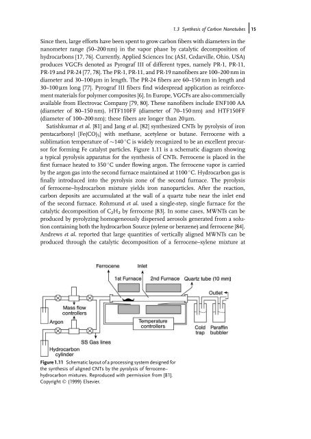
for forming Fe catalyst particles. Figure 1.11 is a schematic diagram showing<br />
a typical pyrolysis apparatus for the synthesis of CNTs. Ferrocene is placed in the<br />
first furnace heated to 350 C under flowing argon. The ferrocene vapor is carried<br />
by the argon gas into the second furnace maintained at 1100 C. Hydrocarbon gas is<br />
finally introduced into the pyrolysis zone of the second furnace. The pyrolysis<br />
of ferrocene–hydrocarbon mixture yields iron nanoparticles. After the reaction,<br />
carbon deposits are accumulated at the wall of a quartz tube near the inlet end<br />
of the second furnace. Rohmund et al. used a single-step, single furnace for the<br />
catalytic decomposition of C 2H 2 by ferrocene [83]. In some cases, MWNTs can be<br />
produced by pyrolyzing homogeneously dispersed aerosols generated from a solution<br />
containing both the hydrocarbon Source (xylene or benzene) <strong>and</strong> ferrocene [84].<br />
Andrews et al. reported that large quantities of vertically aligned MWNTs can be<br />
produced through the catalytic decomposition of a ferrocene–xylene mixture at<br />
Figure 1.11 Schematic layout of a processing system designed for<br />
the synthesis of aligned CNTs by the pyrolysis of ferrocene–<br />
hydrocarbon mixtures. Reproduced with permission from [81].<br />
Copyright Ó (1999) Elsevier.<br />
1.3 Synthesis of <strong>Carbon</strong> <strong>Nanotube</strong>sj15


