Instructions for use: Ikus - Berlin Heart
Instructions for use: Ikus - Berlin Heart
Instructions for use: Ikus - Berlin Heart

You also want an ePaper? Increase the reach of your titles
YUMPU automatically turns print PDFs into web optimized ePapers that Google loves.
Displays and operating elements<br />
Description: Stationary Driving Unit <strong>Ikus</strong><br />
4.2 Displays and operating elements<br />
4.2.1 Connection panel<br />
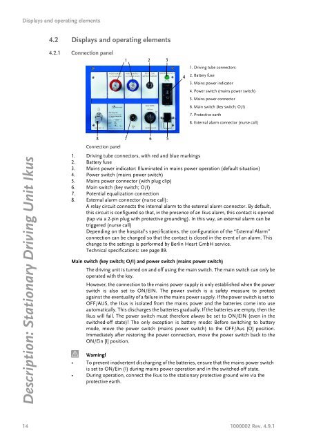
Connection panel<br />
1<br />
2 3<br />
8 7 6 5<br />
1. Driving tube connectors, with red and blue markings<br />
2. Battery f<strong>use</strong><br />
3. Mains power indicator: Illuminated in mains power operation (default situation)<br />
4. Power switch (mains power switch)<br />
5. Mains power connector (with plug clip)<br />
6. Main switch (key switch; O/I)<br />
7. Potential equalization connection<br />
8. External alarm connector (nurse call):<br />
A relay circuit connects the internal alarm to the external alarm connector. By default,<br />
this circuit is configured so that, in the presence of an <strong>Ikus</strong> alarm, this contact is opened<br />
(tap via a 2-pin plug with protective grounding). In this way, an external alarm can be<br />
triggered (nurse call)<br />
Depending on the hospital’s specifications, the configuration of the “External Alarm”<br />
connection can be changed so that the contact is closed in the event of an alarm. This<br />
change to the settings is per<strong>for</strong>med by <strong>Berlin</strong> <strong>Heart</strong> GmbH service.<br />
Technical specifications: see page 89.<br />
Main switch (key switch; O/I) and power switch (mains power switch)<br />
The driving unit is turned on and off using the main switch. The main switch can only be<br />
operated with the key.<br />
However, the connection to the mains power supply is only established when the power<br />
switch is also set to ON/EIN. The power switch is a safety measure to protect<br />
against the eventuality of a failure in the mains power supply. If the power switch is set to<br />
OFF/AUS, the <strong>Ikus</strong> is isolated from the mains power and the batteries come into <strong>use</strong><br />
automatically. This discharges the batteries gradually. If the batteries are empty, then the<br />
<strong>Ikus</strong> will fail. The power switch must there<strong>for</strong>e always be set to ON/EIN (even in the<br />
switched-off state)! The only exception is battery mode: Be<strong>for</strong>e switching to battery<br />
mode, move the power switch (mains power switch) to the OFF/Aus [O] position.<br />
Immediately after restoring the power connection, move the power switch back to the<br />
ON/Ein [I] position.<br />
Warning!<br />
• To prevent inadvertent discharging of the batteries, ensure that the mains power switch<br />
is set to ON/Ein (I) during mains power operation and in the switched-off state.<br />
• During operation, connect the <strong>Ikus</strong> to the stationary protective ground wire via the<br />
protective earth.<br />
14 1000002 Rev. 4.9.1<br />
4<br />
4<br />
1. Driving tube connectors<br />
2. Battery f<strong>use</strong><br />
3. Mains power indicator<br />
4. Power switch (mains power switch)<br />
5. Mains power connector<br />
6. Main switch (key switch; O/I)<br />
7. Protective earth<br />
8. External alarm connector (nurse call)