Instructions for use: Ikus - Berlin Heart
Instructions for use: Ikus - Berlin Heart
Instructions for use: Ikus - Berlin Heart

Create successful ePaper yourself
Turn your PDF publications into a flip-book with our unique Google optimized e-Paper software.
Pump with PU valve<br />
Implantation: Preparation in the operating room<br />
<strong>Instructions</strong><br />
1. Moisten the entire inner surface of the cannula. To do so, bend the cannula slightly, hold<br />
it horizontally, fill it with sterile saline solution and move it slightly backward and <strong>for</strong>ward.<br />
2. Moisten the mandrin with sterile saline solution.<br />
3. Introduce the mandrin straight into the cannula from the outflow side. To do so,<br />
superextend the cannula head slightly. Pull the mandrin <strong>for</strong>ward and backward slightly.<br />
Caution: Avoid rotating movements to prevent damage to the inner surface of the<br />
cannula! Proceed with extreme caution!<br />
4. Situate the mandrin. The mandrin is correctly situated if the cannula head is locked.<br />
Tighten the lock nut of the mandrin to fix the mandrin in place.<br />
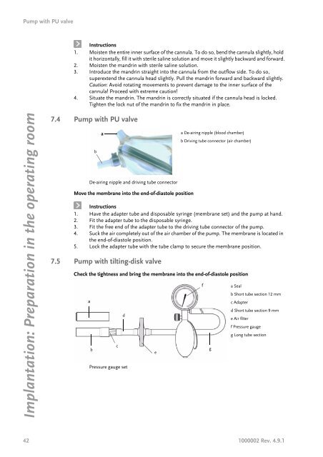
7.4 Pump with PU valve<br />
b<br />
a<br />
De-airing nipple and driving tube connector<br />
Move the membrane into the end-of-diastole position<br />
<strong>Instructions</strong><br />
1. Have the adapter tube and disposable syringe (membrane set) and the pump at hand.<br />
2. Fit the adapter tube to the disposable syringe.<br />
3. Fit the free end of the adapter tube to the driving tube connector of the pump.<br />
4. Suck the air completely out of the air chamber of the pump. The membrane is located in<br />
the end-of-diastole position.<br />
5. Lock the adapter tube with the tube clamp to secure the membrane position.<br />
7.5 Pump with tilting-disk valve<br />
Check the tightness and bring the membrane into the end-of-diastole position<br />
a<br />
b<br />
c<br />
d<br />
Pressure gauge set<br />
a De-airing nipple (blood chamber)<br />
b Driving tube connector (air chamber)<br />
42 1000002 Rev. 4.9.1<br />
e<br />
f<br />
g<br />
a Seal<br />
b Short tube section 12 mm<br />
c Adapter<br />
d Short tube section 9 mm<br />
e Air filter<br />
f Pressure gauge<br />
g Long tube section