- Page 1 and 2:
Report SeriesTomeArchitectureand ma
- Page 3 and 4:
C.RP.ADP.04.00013/495ContentsConten
- Page 5 and 6:
C.RP.ADP.04.00015/4955.3.2 Design p
- Page 7 and 8:
C.RP.ADP.04.00017/4959.2.3 The tran
- Page 9 and 10:
C.RP.ADP.04.00019/495Bibliographic
- Page 11 and 12:
C.RP.ADP.04.000111/495Table of illu
- Page 13 and 14:
C.RP.ADP.04.000113/495Figure 4.3.8
- Page 15 and 16:
C.RP.ADP.04.000115/495Figure 5.3.9F
- Page 17 and 18:
C.RP.ADP.04.000117/495Figure 9.2.2
- Page 19 and 20:
C.RP.ADP.04.000119/495Figure 10.4.8
- Page 21:
C.RP.ADP.04.000121/495Table 11.6.1T
- Page 24 and 25:
1 - The Study Approach1.1 Purpose o
- Page 26 and 27:
1 - The Study ApproachFrom 1999 to
- Page 28 and 29:
1 - The Study Approach1.4 Structure
- Page 30 and 31:
2 - General DescriptionThis chapter
- Page 32 and 33:
2 - General DescriptionHLLL waste p
- Page 34 and 35:
2 - General DescriptionFor a transi
- Page 36 and 37:
2 - General DescriptionIt should al
- Page 38 and 39:
2 - General Description2.2.2.2 Safe
- Page 40 and 41:
2 - General DescriptionThe protecti
- Page 42 and 43:
2 - General DescriptionIt should al
- Page 44 and 45:
2 - General DescriptionThis section
- Page 46 and 47:
2 - General Descriptionfollowing th
- Page 48 and 49:
2 - General Description2.3.2.2 Geoc
- Page 50 and 51:
2 - General DescriptionFigure 2.3.5
- Page 52 and 53:
2 - General DescriptionIn the Dogge
- Page 54 and 55:
2 - General DescriptionFigure 2.4.1
- Page 56 and 57:
2 - General Description• A dimens
- Page 58 and 59:
2 - General Description2.4.1.2 Desi
- Page 60 and 61:
2 - General DescriptionFigure 2.4.4
- Page 62 and 63:
2 - General DescriptionFigure 2.4.6
- Page 64 and 65:
2 - General DescriptionFigure 2.4.8
- Page 66 and 67:
2 - General Description- some conne
- Page 68 and 69:
2 - General DescriptionAs for the w
- Page 70 and 71:
2 - General DescriptionThe figure b
- Page 73 and 74:
33High-level long-lived waste3.1 Wa
- Page 75 and 76:
3 - High Level Long-Lived WasteRese
- Page 77 and 78:
3 - High Level Long-Lived Wastesupp
- Page 79 and 80:
3 - High Level Long-Lived WasteThe
- Page 81 and 82:
3 - High Level Long-Lived WasteFigu
- Page 83 and 84:
3 - High Level Long-Lived WasteA fi
- Page 85 and 86:
3 - High Level Long-Lived WasteThe
- Page 87 and 88:
3 - High Level Long-Lived WasteFigu
- Page 89 and 90:
3 - High Level Long-Lived WasteA se
- Page 91 and 92:
3 - High Level Long-Lived WasteVitr
- Page 93 and 94:
3 - High Level Long-Lived WasteFigu
- Page 95 and 96:
3 - High Level Long-Lived WasteCond
- Page 97 and 98: 3 - High Level Long-Lived WasteThe
- Page 99 and 100: 3 - High Level Long-Lived WasteDist
- Page 101 and 102: 3 - High Level Long-Lived Waste3.3.
- Page 103 and 104: 3 - High Level Long-Lived WasteTabl
- Page 105 and 106: 44Waste disposal packages4.1 B disp
- Page 107 and 108: 4 - Waste disposal PackagesFor empl
- Page 109 and 110: 4 - Waste disposal Packages• Safe
- Page 111 and 112: 4 - Waste disposal Packages• "Par
- Page 113 and 114: 4 - Waste disposal PackagesThe prin
- Page 115 and 116: 4 - Waste disposal PackagesThe seco
- Page 117 and 118: 4 - Waste disposal PackagesFigure 4
- Page 119 and 120: 4 - Waste disposal PackagesFigure 4
- Page 121: 4 - Waste disposal Packages4.1.5 Th
- Page 124 and 125: 4 - Waste disposal Packages4.1.5.7
- Page 126 and 127: 4 - Waste disposal PackagesFigure 4
- Page 128 and 129: 4 - Waste disposal PackagesIn the c
- Page 130 and 131: 4 - Waste disposal PackagesFinally,
- Page 132 and 133: 4 - Waste disposal PackagesThe YAG
- Page 134 and 135: 4 - Waste disposal PackagesIn the U
- Page 136 and 137: 4 - Waste disposal Packages4.2.3.2
- Page 138 and 139: 4 - Waste disposal PackagesThe spee
- Page 140 and 141: 4 - Waste disposal Packages4.2.4 Ma
- Page 142 and 143: 4 - Waste disposal PackagesLoadSlid
- Page 144 and 145: 4 - Waste disposal Packages4.3 Spen
- Page 146 and 147: 4 - Waste disposal PackagesThe seco
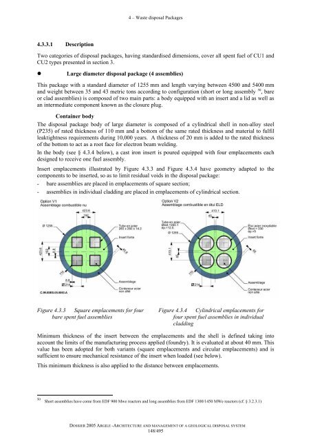
- Page 150 and 151: 4 - Waste disposal PackagesFor both
- Page 152 and 153: 4 - Waste disposal Packages• Safe
- Page 154 and 155: 4 - Waste disposal PackagesAs for C
- Page 156 and 157: 4 - Waste disposal PackagesMelted c
- Page 159 and 160: 55Repository modules.5.1 B waste re
- Page 161 and 162: 5 - Repository Modules5.1.1.1 Quest
- Page 163 and 164: 5 - Repository Modules• Controlli
- Page 165 and 166: 5 - Repository ModulesFigure 5.1.1t
- Page 167 and 168: 5 - Repository Modules• The geome
- Page 169 and 170: 5 - Repository ModulesTable 5.1.1Fu
- Page 171 and 172: 5 - Repository ModulesFigure 5.1.9D
- Page 173 and 174: 5 - Repository Modules5.1.3.2 Detai
- Page 175 and 176: 5 - Repository Modules• Arrangeme
- Page 177 and 178: 5 - Repository ModulesAlthough this
- Page 179 and 180: 5 - Repository ModulesConnection be
- Page 181 and 182: 5 - Repository ModulesFurthermore,
- Page 183 and 184: 5 - Repository ModulesTo illustrate
- Page 185 and 186: 5 - Repository Modules• The acces
- Page 187 and 188: 5 - Repository ModulesFigure 5.1.24
- Page 189 and 190: 5 - Repository ModulesFigure 5.1.26
- Page 191 and 192: 5 - Repository Modules• Limiting
- Page 193 and 194: 5 - Repository Modules5.2.2 Design
- Page 195 and 196: 5 - Repository ModulesA concept wit
- Page 197 and 198: 5 - Repository Modules• Orientati
- Page 199 and 200:
5 - Repository ModulesFigure 5.2.3O
- Page 201 and 202:
5 - Repository Modules5.2.3.1 Descr
- Page 203 and 204:
5 - Repository ModulesA minimum ann
- Page 205 and 206:
5 - Repository ModulesIn terms of t
- Page 207 and 208:
5 - Repository ModulesStorage perio
- Page 209 and 210:
5 - Repository ModulesFigure 5.2.13
- Page 211 and 212:
5 - Repository ModulesSensitivity t
- Page 213 and 214:
5 - Repository ModulesIt must be no
- Page 215 and 216:
5 - Repository Modules• Disposal
- Page 217 and 218:
5 - Repository ModulesFigure 5.2.18
- Page 219 and 220:
5 - Repository Modules• Assembly
- Page 221 and 222:
5 - Repository ModulesFigure 5.2.21
- Page 223 and 224:
5 - Repository ModulesThe permeabil
- Page 225 and 226:
5 - Repository ModulesThe evolution
- Page 227 and 228:
5 - Repository ModulesThe lowest dr
- Page 229 and 230:
5 - Repository Modules• Back-fill
- Page 231 and 232:
5 - Repository Modules5.3.2.1 Sever
- Page 233 and 234:
5 - Repository ModulesFigure 5.3.4S
- Page 235 and 236:
5 - Repository ModulesThe cells are
- Page 237 and 238:
5 - Repository ModulesFigure 5.3.8
- Page 239 and 240:
5 - Repository ModulesFinally, it s
- Page 241 and 242:
5 - Repository ModulesThe internal
- Page 243 and 244:
5 - Repository Modules• Descripti
- Page 245 and 246:
5 - Repository ModulesFigure 5.3.14
- Page 247 and 248:
5 - Repository ModulesFigure 5.3.17
- Page 249 and 250:
5 - Repository Modules- another pos
- Page 251 and 252:
66 Overall undergroundarchitecture6
- Page 253 and 254:
6 - Overall underground architectur
- Page 255 and 256:
6 - Overall underground architectur
- Page 257 and 258:
6 - Overall underground architectur
- Page 259 and 260:
6 - Overall underground architectur
- Page 261 and 262:
6 - Overall underground architectur
- Page 263 and 264:
6 - Overall underground architectur
- Page 265 and 266:
6 - Overall underground architectur
- Page 267 and 268:
6 - Overall underground architectur
- Page 269 and 270:
6 - Overall underground architectur
- Page 271 and 272:
6 - Overall underground architectur
- Page 273 and 274:
6 - Overall underground architectur
- Page 275 and 276:
6 - Overall underground architectur
- Page 277 and 278:
6 - Overall underground architectur
- Page 279 and 280:
6 - Overall underground architectur
- Page 281 and 282:
6 - Overall underground architectur
- Page 283 and 284:
6 - Overall underground architectur
- Page 285 and 286:
6 - Overall underground architectur
- Page 287:
6 - Overall underground architectur
- Page 290 and 291:
7 - The shafts and the driftsThe co
- Page 292 and 293:
7 - The shafts and the drifts7.2.2
- Page 294 and 295:
7 - The shafts and the driftsFigure
- Page 296 and 297:
7 - The shafts and the drifts7.3.3.
- Page 298 and 299:
7 - The shafts and the drifts7.3.4.
- Page 300 and 301:
7 - The shafts and the drifts7.4 De
- Page 302 and 303:
7 - The shafts and the driftsFigure
- Page 304 and 305:
7 - The shafts and the driftsThe dr
- Page 306 and 307:
7 - The shafts and the driftsFigure
- Page 308 and 309:
7 - The shafts and the drifts7.7 Cl
- Page 310 and 311:
7 - The shafts and the drifts7.7.2.
- Page 312 and 313:
7 - The shafts and the driftspressu
- Page 314 and 315:
7 - The shafts and the drifts7.7.2.
- Page 316 and 317:
7 - The shafts and the driftsFigure
- Page 318 and 319:
7 - The shafts and the drifts7.7.3.
- Page 321 and 322:
88Surface installations8.1 General
- Page 323 and 324:
8 - Surface installationsFigure 8.1
- Page 325 and 326:
8 - Surface installationsSuch a bui
- Page 327:
8 - Surface installationsApart from
- Page 330 and 331:
9 - Nuclear operating resources in
- Page 332 and 333:
9 - Nuclear operating resources in
- Page 334 and 335:
9 - Nuclear operating resources in
- Page 336 and 337:
9 - Nuclear operating resources in
- Page 338 and 339:
9 - Nuclear operating resources in
- Page 340 and 341:
9 - Nuclear operating resources in
- Page 342 and 343:
9 - Nuclear operating resources in
- Page 344 and 345:
9 - Nuclear operating resources in
- Page 346 and 347:
9 - Nuclear operating resources in
- Page 348 and 349:
9 - Nuclear operating resources in
- Page 350 and 351:
9 - Nuclear operating resources in
- Page 352 and 353:
9 - Nuclear operating resources in
- Page 354 and 355:
9 - Nuclear operating resources in
- Page 356 and 357:
9 - Nuclear operating resources in
- Page 358 and 359:
9 - Nuclear operating resources in
- Page 360 and 361:
9 - Nuclear operating resources in
- Page 362 and 363:
9 - Nuclear operating resources in
- Page 365 and 366:
1010 Reversible repositorymanagemen
- Page 367 and 368:
During the operational phase, the d
- Page 369 and 370:
Figure 10.1.1Key repository operati
- Page 371 and 372:
The radioactive elements can thus b
- Page 373 and 374:
Furthermore, equipment and liner ma
- Page 375 and 376:
The condition of the access drifts
- Page 377 and 378:
The sleeve’s durability is improv
- Page 379 and 380:
10.2.2.2 “Post cell-sealing” st
- Page 381 and 382:
As far as long-term safety is conce
- Page 383 and 384:
Figure 10.2.10Diagrammatic represen
- Page 385 and 386:
10.3.1.1 Overview of the principal
- Page 387 and 388:
10.3.2.2 Monitoring of type C waste
- Page 389 and 390:
The project’s monitoring programm
- Page 391 and 392:
• Absence of a significant impact
- Page 393 and 394:
Dams are of particular interest whe
- Page 395 and 396:
The rate of operation of these sens
- Page 397 and 398:
• Water contentThe water content
- Page 399 and 400:
A similar wireless transmission tec
- Page 401 and 402:
Figure 10.3.9Example of monitoring
- Page 403 and 404:
In addition, a visual control syste
- Page 405 and 406:
Cell atmosphere monitoring is limit
- Page 407 and 408:
The monitoring of the seal can be c
- Page 409 and 410:
• The instrumented sections and t
- Page 411 and 412:
The deformation measurements carrie
- Page 413 and 414:
10.3.9 Observation of spent fuel di
- Page 415 and 416:
These instrumented sections (cf. §
- Page 417 and 418:
The monitoring equipment embedded i
- Page 419 and 420:
the cell which conditions the evolu
- Page 421 and 422:
Figure 10.4.2Cell filled with B pac
- Page 423 and 424:
Ventilation of a 250-m long cell re
- Page 425 and 426:
• Package retrieval processOnce t
- Page 427 and 428:
Figure 10.4.10C Cell at end of oper
- Page 429 and 430:
The robot is traversed similarly to
- Page 431 and 432:
This operation is complete when a b
- Page 433 and 434:
The condition of the drift liner sh
- Page 435 and 436:
1111 Operational Safety11.1 Evaluat
- Page 437 and 438:
11 - Operational SafetyTransport tr
- Page 439 and 440:
11 - Operational SafetyTable 11.1.1
- Page 441 and 442:
11 - Operational SafetyResultsTable
- Page 443 and 444:
11 - Operational SafetyThe risks ar
- Page 445 and 446:
11 - Operational SafetyTable 11.2.1
- Page 447 and 448:
11 - Operational SafetyOn the surfa
- Page 449 and 450:
11 - Operational Safety“Honeycomb
- Page 451 and 452:
11 - Operational SafetyGiven the me
- Page 453 and 454:
11 - Operational SafetyThis risk co
- Page 455 and 456:
11 - Operational SafetyHydrogen emi
- Page 457 and 458:
11 - Operational SafetyOver and abo
- Page 459 and 460:
11 - Operational SafetyFigure 11.4.
- Page 461 and 462:
11 - Operational SafetyFigure 11.4.
- Page 463 and 464:
11 - Operational SafetyHowever, wit
- Page 465 and 466:
11 - Operational SafetyTable 11.5.1
- Page 467 and 468:
11 - Operational SafetyFigure 11.5.
- Page 469 and 470:
11 - Operational Safety11.5.2 Concl
- Page 471 and 472:
11 - Operational SafetyFigure 11.6.
- Page 473 and 474:
11 - Operational Safety11.7.1 Asses
- Page 475 and 476:
11 - Operational SafetyTable 11.7.2
- Page 477 and 478:
11 - Operational SafetySuch a damag
- Page 479 and 480:
11 - Operational Safety11.8.1.2 Dat
- Page 481 and 482:
11 - Operational SafetyIn all cases
- Page 483 and 484:
1212 Synthesis12.1 Simple and robus
- Page 485 and 486:
12 - SynthesisThe existence of unce
- Page 487:
12 - SynthesisTo concretely illustr
- Page 490 and 491:
Bibliographic references[17] Callon
- Page 492 and 493:
Bibliographic references[54] Andra
- Page 494 and 495:
Bibliographic references[88] IAEA (
- Page 496 and 497:
Photo Credits:ANDRA - AREVA CREATIV


