- Page 1 and 2:
LISTING OF APPENDICES. A Master Loc
- Page 3 and 4:
I-FWD-3 COMFLTFORCOMINST 4790.3 REV
- Page 5 and 6:
I-FWD-5 COMFLTFORCOMINST 4790.3 REV
- Page 7 and 8:
I-FWD-7 COMFLTFORCOMINST 4790.3 REV
- Page 9 and 10:
APPENDIX A MASTER LOCATOR GUIDE FOR
- Page 11 and 12:
CHAPTER 4 TYPE COMMANDER MAINTENANC
- Page 13 and 14:
2.3 Assessment Results 2.4 Responsi
- Page 15 and 16:
17.5 Safety Procedures 17.6 Catapul
- Page 17 and 18:
CHAPTER 6 MATERIAL CONTROL 6.1 Purp
- Page 19 and 20:
CHAPTER 8 DEPARTURE FROM SPECIFICAT
- Page 21 and 22:
CHAPTER 10 MOTOR GASOLINE HANDLING
- Page 23 and 24:
CHAPTER 27 SCHEDULED PRESERVATION U
- Page 25 and 26:
CHAPTER 2 CONTRACTS AND CONTRACT AD
- Page 27 and 28:
APPENDIX B MASTER LIST OF REFERENCE
- Page 29 and 30:
I-FWD-B-3 COMFLTFORCOMINST 4790.3 R
- Page 31 and 32:
FAR 203 FAR Part 1.3 - Agency Acqui
- Page 33 and 34:
I-FWD-B-7 COMFLTFORCOMINST 4790.3 R
- Page 35 and 36:
I-FWD-B-9 COMFLTFORCOMINST 4790.3 R
- Page 37 and 38:
NAVSEA SI 009-04 - Quality Manageme
- Page 39 and 40:
NAVSEAINST 5730.1 - Legislative and
- Page 41 and 42:
I-FWD-B-15 COMFLTFORCOMINST 4790.3
- Page 43 and 44:
APPENDIX C RESPONSIBILITIES Fleet C
- Page 45 and 46:
Type Commander (TYCOM) Section Area
- Page 47 and 48:
I-FWD-C-5 COMFLTFORCOMINST 4790.3 R
- Page 49 and 50:
VI-9.2.2 Metrology and Calibration
- Page 51 and 52:
Immediate Superior in Command (ISIC
- Page 53 and 54:
V-I-1.4.1 Organizational Responsibi
- Page 55 and 56:
VI-7.2.2 Board of Inspection and Su
- Page 57 and 58:
I-FWD-C-15 COMFLTFORCOMINST 4790.3
- Page 59 and 60:
Regional Maintenance Center Command
- Page 61 and 62:
Ship's Commanding Officer Section A
- Page 63 and 64:
I-FWD-C-21 COMFLTFORCOMINST 4790.3
- Page 65 and 66:
VI-8.2.3 Miniature/Micro-miniature
- Page 67 and 68:
I-FWD-C-25 COMFLTFORCOMINST 4790.3
- Page 69 and 70:
I-FWD-C-27 COMFLTFORCOMINST 4790.3
- Page 71 and 72:
Controlled Material Petty Officer S
- Page 73 and 74:
JOINT FLEET MAINTENANCE MANUAL VOLU
- Page 75 and 76:
iii COMFLTFORCOMINST 4790.3 REV A C
- Page 77 and 78:
JOINT FLEET MAINTENANCE MANUAL VOLU
- Page 79 and 80:
vii COMFLTFORCOMINST 4790.3 REV A C
- Page 81 and 82:
ix COMFLTFORCOMINST 4790.3 REV A CH
- Page 83 and 84:
FOREWORD JOINT FLEET MAINTENANCE MA
- Page 85 and 86:
xiii COMFLTFORCOMINST 4790.3 REV A
- Page 87 and 88:
xv COMFLTFORCOMINST 4790.3 REV A CH
- Page 89 and 90:
xvii COMFLTFORCOMINST 4790.3 REV A
- Page 91 and 92:
REFERENCES. VOLUME I CHAPTER 1 INTR
- Page 93 and 94:
APPENDIX A1 SUMMARY OF TYPICAL NEW
- Page 95 and 96:
APPENDIX A2 SUMMARY OF TYPICAL NEW
- Page 97 and 98:
Event APPENDIX A3 SUMMARY OF TYPICA
- Page 99 and 100:
I-1B-1 COMFLTFORCOMINST 4790.3 REV
- Page 101 and 102:
I-1B-3 COMFLTFORCOMINST 4790.3 REV
- Page 103 and 104:
I-1B-5 COMFLTFORCOMINST 4790.3 REV
- Page 105 and 106:
-82 Months Begin Construction -6 Mo
- Page 107 and 108:
APPENDIX C LIST OF ACRONYMS 2M Mini
- Page 109 and 110:
MACHALT Machinery Alteration MBT Ma
- Page 111 and 112:
TERM DEFINITION APPENDIX D GLOSSARY
- Page 113 and 114:
COMFLTFORCOMINST 4790.3 REV A CH-2
- Page 115 and 116:
REFERENCES. VOLUME I CHAPTER 2 POLI
- Page 117 and 118:
COMFLTFORCOMINST 4790.3 REV A CH-1
- Page 119 and 120:
COMFLTFORCOMINST 4790.3 REV A CH-1
- Page 121 and 122:
COMFLTFORCOMINST 4790.3 REV A CH-1
- Page 123 and 124:
COMFLTFORCOMINST 4790.3 REV A CH-1
- Page 125 and 126:
COMFLTFORCOMINST 4790.3 REV A CH-5
- Page 127 and 128:
COMFLTFORCOMINST 4790.3 REV A CH-1
- Page 129 and 130:
COMFLTFORCOMINST 4790.3 REV A CH-1
- Page 131 and 132:
COMFLTFORCOMINST 4790.3 REV A CH-1
- Page 133 and 134:
COMFLTFORCOMINST 4790.3 REV A CH-1
- Page 135 and 136:
COMFLTFORCOMINST 4790.3 REV A CH-1
- Page 137 and 138:
COMFLTFORCOMINST 4790.3 REV A CH-3
- Page 139 and 140:
COMFLTFORCOMINST 4790.3 REV A CH-1
- Page 141 and 142:
MSG RCMD IN-SERVICE MSG INFO SHIP P
- Page 143 and 144:
APPENDIX A2 I-2A-3 COMFLTFORCOMINST
- Page 145 and 146:
APPENDIX A4 I-2A-5 COMFLTFORCOMINST
- Page 147 and 148:
APPENDIX A5 I-2A-7 COMFLTFORCOMINST
- Page 149 and 150:
APPENDIX A7 SAMPLE CNO TO SHIP PROG
- Page 151 and 152:
APPENDIX A9 SAMPLE SHIP PROGRAM MAN
- Page 153 and 154:
MSG PCU READY FOR FAST CRUISE & ALP
- Page 155 and 156:
APPENDIX B2 I-2B-3 COMFLTFORCOMINST
- Page 157 and 158:
APPENDIX B4 I-2B-5 COMFLTFORCOMINST
- Page 159 and 160:
APPENDIX B6 I-2B-7 COMFLTFORCOMINST
- Page 161 and 162:
APPENDIX B8 SAMPLE NAVSEA TO TYCOM
- Page 163 and 164:
APPENDIX C COMFLTFORCOMINST 4790.3
- Page 165 and 166:
APPENDIX C2 SAMPLE NAVSEA TO TYCOM
- Page 167 and 168:
APPENDIX D Message Scenario and Sam
- Page 169 and 170:
COMFLTFORCOMINST 4790.3 REV A CH-3
- Page 171 and 172:
APPENDIX D3 COMFLTFORCOMINST 4790.3
- Page 173 and 174:
APPENDIX E COMFLTFORCOMINST 4790.3
- Page 175 and 176:
APPENDIX F COMFLTFORCOMINST 4790.3
- Page 177 and 178:
APPENDIX G COMFLTFORCOMINST 4790.3
- Page 179 and 180:
Concurrence PCO NRRO APPENDIX H Pre
- Page 181 and 182:
APPENDIX H2 SAMPLE SUPERVISING AUTH
- Page 183 and 184:
APPENDIX I COMFLTFORCOMINST 4790.3
- Page 185 and 186:
APPENDIX J COMFLTFORCOMINST 4790.3
- Page 187 and 188:
APPENDIX K COMFLTFORCOMINST 4790.3
- Page 189 and 190:
APPENDIX L COMFLTFORCOMINST 4790.3
- Page 191 and 192:
APPENDIX M COMFLTFORCOMINST 4790.3
- Page 193 and 194:
APPENDIX N COMFLTFORCOMINST 4790.3
- Page 195 and 196:
APPENDIX O COMFLTFORCOMINST 4790.3
- Page 197 and 198:
APPENDIX P SAMPLE TYCOM MESSAGE TO
- Page 199 and 200:
APPENDIX Q COMFLTFORCOMINST 4790.3
- Page 201 and 202: APPENDIX R COMFLTFORCOMINST 4790.3
- Page 203 and 204: APPENDIX S COMFLTFORCOMINST 4790.3
- Page 205 and 206: APPENDIX T COMFLTFORCOMINST 4790.3
- Page 207 and 208: APPENDIX U COMFLTFORCOMINST 4790.3
- Page 209 and 210: APPENDIX V COMFLTFORCOMINST 4790.3
- Page 211 and 212: APPENDIX W COMFLTFORCOMINST 4790.3
- Page 213 and 214: APPENDIX X COMFLTFORCOMINST 4790.3
- Page 215 and 216: APPENDIX Y COMFLTFORCOMINST 4790.3
- Page 217 and 218: APPENDIX Z COMFLTFORCOMINST 4790.3
- Page 219 and 220: The TYCOM/ISIC is responsible for t
- Page 221 and 222: APPENDIX AB COMFLTFORCOMINST 4790.3
- Page 223 and 224: COMFLTFORCOMINST 4790.3 REV A CH-1
- Page 225 and 226: APPENDIX AC COMFLTFORCOMINST 4790.3
- Page 227 and 228: APPENDIX AD GENERIC BASE LINE OF FL
- Page 229 and 230: • Navigation • Combat Systems C
- Page 231 and 232: COMFLTFORCOMINST 4790.3 REV A CH-1
- Page 233 and 234: APPENDIX AE COMFLTFORCOMINST 4790.3
- Page 235 and 236: APPENDIX AF COMFLTFORCOMINST 4790.3
- Page 237 and 238: APPENDIX AG COMFLTFORCOMINST 4790.3
- Page 239 and 240: REFERENCES. VOLUME I CHAPTER 3 PRE
- Page 241 and 242: 3.3.2 Periodic Monitoring/Inspectio
- Page 243 and 244: COMFLTFORCOMINST 4790.3 REV A 3.3.5
- Page 245 and 246: 3.3.9 National Policy on the Contro
- Page 247 and 248: 3.3.14 Light-Off Assessment (Non-Nu
- Page 249 and 250: COMFLTFORCOMINST 4790.3 REV A CH-3
- Page 251: COMFLTFORCOMINST 4790.3 REV A a. Sh
- Page 255 and 256: APPENDIX A AREAS TO BE EVALUATED DU
- Page 257 and 258: COMFLTFORCOMINST 4790.3 REV A d. Fu
- Page 259 and 260: APPENDIX B AREAS TO BE EVALUATED DU
- Page 261 and 262: APPENDIX C COMFLTFORCOMINST 4790.3
- Page 263 and 264: PRE-RSE SCHEDULE OF EXAMINATION COM
- Page 265 and 266: Encl (3) I-3C-5 Name Rate/NEC Repor
- Page 267 and 268: Encl (3) I-3C-7 Name Rate/NEC Repor
- Page 269 and 270: EOOW EWS ERS RO EO RT AEA CH/CD ELT
- Page 271 and 272: INTERVIEWER - A___________ SUBJECT
- Page 273 and 274: INTERVIEWER - C -________________ S
- Page 275 and 276: SAMPLE INTERVIEW SCHEDULE INTERVIEW
- Page 277 and 278: SAMPLE STATUS OF PROPULSION PLANT S
- Page 279 and 280: Departmental SAMPLE STATUS OF PROPU
- Page 281 and 282: APPENDIX D IN-SERVICE COMPARTMENT S
- Page 283 and 284: APPENDIX E SAMPLE PRE-COMMISSIONING
- Page 285 and 286: COMFLTFORCOMINST 4790.3 REV A SAMPL
- Page 287 and 288: COMFLTFORCOMINST 4790.3 REV A SAMPL
- Page 289 and 290: COMFLTFORCOMINST 4790.3 REV A SAMPL
- Page 291 and 292: COMFLTFORCOMINST 4790.3 REV A SAMPL
- Page 293 and 294: COMFLTFORCOMINST 4790.3 REV A SAMPL
- Page 295 and 296: COMFLTFORCOMINST 4790.3 REV A SAMPL
- Page 297 and 298: COMFLTFORCOMINST 4790.3 REV A SAMPL
- Page 299 and 300: COMFLTFORCOMINST 4790.3 REV A SAMPL
- Page 301 and 302: REFERENCES. VOLUME I CHAPTER 4 TRIA
- Page 303 and 304:
I-4-3 COMFLTFORCOMINST 4790.3 REV A
- Page 305 and 306:
I-4-5 COMFLTFORCOMINST 4790.3 REV A
- Page 307 and 308:
I-4-7 COMFLTFORCOMINST 4790.3 REV A
- Page 309 and 310:
I-4-9 COMFLTFORCOMINST 4790.3 REV A
- Page 311 and 312:
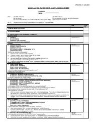
APPENDIX A SPECIFIC DOCK TRIAL TEST
- Page 313 and 314:
I-4A-3 COMFLTFORCOMINST 4790.3 REV
- Page 315 and 316:
I-4A-5 COMFLTFORCOMINST 4790.3 REV
- Page 317 and 318:
I-4A-7 COMFLTFORCOMINST 4790.3 REV
- Page 319 and 320:
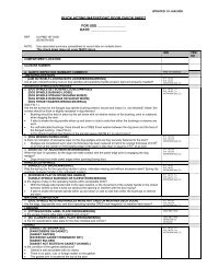
APPENDIX B MINIMUM FAST CRUISE REQU
- Page 321 and 322:
I-4B-3 COMFLTFORCOMINST 4790.3 REV
- Page 323 and 324:
APPENDIX C I-4C-1 COMFLTFORCOMINST
- Page 325 and 326:
g. Environmental Protection Collect
- Page 327 and 328:
APPENDIX D LISTING OF TESTS TO BE P
- Page 329 and 330:
I-4D-3 COMFLTFORCOMINST 4790.3 REV
- Page 331 and 332:
1. Radio Communication: APPENDIX E
- Page 333 and 334:
APPENDIX F LISTING OF TESTS TO BE P
- Page 335 and 336:
I-4F-3 COMFLTFORCOMINST 4790.3 REV
- Page 337 and 338:
I-4F-5 COMFLTFORCOMINST 4790.3 REV
- Page 339 and 340:
I-4F-7 COMFLTFORCOMINST 4790.3 REV
- Page 341 and 342:
APPENDIX G SUBMARINE SEA TRIAL SITU
- Page 343 and 344:
REFERENCES. VOLUME I CHAPTER 5 POST
- Page 345 and 346:
(4) CSCT. (5) Silencing Deficiencie
- Page 347 and 348:
COMFLTFORCOMINST 4790.3 REV A 5.5 G
- Page 349 and 350:
I-5A-1 USS_________________________
- Page 351 and 352:
APPENDIX B COMFLTFORCOMINST 4790.3
- Page 353 and 354:
Key Used In The Following Columns D
- Page 355 and 356:
APPENDIX C COMFLTFORCOMINST 4790.3
- Page 357 and 358:
REFERENCES. VOLUME I CHAPTER 6 POST
- Page 359 and 360:
6.4.2 Assignment of Escort Ship (Su
- Page 361 and 362:
NOTE: BUILDER TRIALS CORRECT DEFICI
- Page 363 and 364:
APPENDIX B COMFLTFORCOMINST 4790.3
- Page 365 and 366:
Time Event COMFLTFORCOMINST 4790.3
- Page 367 and 368:
APPENDIX C COMFLTFORCOMINST 4790.3
- Page 369 and 370:
APPENDIX D COMFLTFORCOMINST 4790.3
- Page 371 and 372:
COMFLTFORCOMINST 4790.3 REV A CH-3