- Page 1 and 2:
RAILROAD & CO. ® TrainController
- Page 3 and 4:
Contact: Freiwald Software Kreuzber
- Page 5 and 6:
4 Schedule ........................
- Page 7 and 8:
6 5.8 Arranging Indicators and Mark
- Page 9 and 10:
13 The Clock ......................
- Page 11 and 12:
10 Passing trains from automatic to
- Page 13 and 14:
! Some sections or paragraphs are h
- Page 15 and 16:
14 tal system is required to resolv
- Page 17 and 18:
28. New train operations allow to r
- Page 19 and 20:
51. A optional schedule rule causes
- Page 21 and 22:
74. Conditions and triggers may now
- Page 24 and 25:
Part I Quick Start B 23
- Page 26 and 27:
Diagram 1: TrainController Setup Sc
- Page 28 and 29:
Diagram 3: Setup Digital Systems di
- Page 30 and 31:
Diagram 5: Train Window If you want
- Page 32 and 33:
Diagram 8: Entering a Name You may
- Page 34 and 35:
Quick Start - Step 3: Controlling T
- Page 36 and 37:
Diagram 13: Track section with turn
- Page 38 and 39:
played image of the turnout and the
- Page 40 and 41:
Dividing the layout into Blocks Ano
- Page 42 and 43:
If everything was done correctly, t
- Page 44 and 45:
Diagram 23: Block Editor with Conta
- Page 46 and 47:
If this has been done correctly, th
- Page 48 and 49:
testing this on a bigger layout ens
- Page 50 and 51:
Quick Start - Step 5: Controlling T
- Page 52 and 53:
Diagram 33: Block Editor Click on t
- Page 54 and 55:
Diagram 35: Block Editor Click on t
- Page 56 and 57:
section 3.5, “The Speed Profile
- Page 58 and 59:
To do this run our train manually b
- Page 60 and 61:
Diagram 41: Locking the left Entry
- Page 62 and 63:
Next select “Block 4” and press
- Page 64:
However, TrainController is able to
- Page 67 and 68:
B 66 1 Introduction 1.1 Overview Tr
- Page 69 and 70:
In all, TrainController provides th
- Page 71 and 72:
70 Diagram 47: RAILROAD & CO. Train
- Page 73 and 74:
from its current position to the de
- Page 75 and 76:
• Well suited, too, to predefine
- Page 77 and 78:
76 Feature (1) Block Securing Yes Y
- Page 79 and 80:
78 User Interface Design The user i
- Page 81 and 82:
80 Diagram 48: Docking a Train Wind
- Page 83 and 84:
! The current layout and settings o
- Page 85 and 86:
You first insert track elements int
- Page 87 and 88:
Trains can run under full manual co
- Page 89 and 90:
B • Accessory elements of several
- Page 91 and 92:
90 Diagram 52: US CTC Panel Style D
- Page 93 and 94:
outes. The possibilities to apply d
- Page 95 and 96:
• Three way turnout • Single or
- Page 97 and 98:
! 96 Diagram 63: Specifying the nam
- Page 99 and 100:
The image above displays two possib
- Page 101 and 102:
100 Accessories Accessory elements
- Page 103 and 104:
102 Images It is possible to displa
- Page 105 and 106:
B 104 3 Train Control 3.1 Introduct
- Page 107 and 108: B 106 Train List The The Train List
- Page 109 and 110: 108 Diagram 72: Digital Address of
- Page 111 and 112: the right on the layout, when the d
- Page 113 and 114: ! B • Set the start voltage to a
- Page 115 and 116: X ! 114 Advanced Fine Tuning of the
- Page 117 and 118: ! the measurement and indicator “
- Page 119 and 120: The speed profile can also be viewe
- Page 121 and 122: maximum profile value, which repres
- Page 123 and 124: • when a schedule is executed (se
- Page 125 and 126: different engines and trains can re
- Page 127 and 128: ! ! back to the digital system. Suc
- Page 129 and 130: tain track section. In Diagram 85 t
- Page 131 and 132: ! 130 Diagram 87: Train is still lo
- Page 133 and 134: Usually each track in a station or
- Page 135 and 136: 134 Diagram 90: Track Plan of the S
- Page 137 and 138: Typical examples of blocks are •
- Page 139 and 140: of the blocks in the track diagram
- Page 141 and 142: For specific purposes it is also po
- Page 143 and 144: B aware, that trains can travel fro
- Page 145 and 146: ! B The orientation of each engine
- Page 147 and 148: gine orientation accordingly even i
- Page 149 and 150: 148 5.5 Train Detection and Train T
- Page 151 and 152: 150 Diagram 100: Specifying the dig
- Page 153 and 154: B 152 Registration of unknown Train
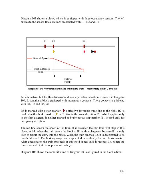
- Page 155 and 156: B 154 5.6 Blocks and Indicators For
- Page 157: train will stop inside the block fo
- Page 161 and 162: ! B B TrainController assumes that
- Page 163 and 164: Diagram 106 shows a block equipped
- Page 165 and 166: Diagram 109 has been derived from D
- Page 167 and 168: ! 166 Diagram 112: Editing Shifted
- Page 169 and 170: • Add a further stop marker to th
- Page 171 and 172: entered. The brake and stop indicat
- Page 173 and 174: ! 172 How Block Signals Work The fo
- Page 175 and 176: B 174 5.11 Schedules Schedule Diagr
- Page 177 and 178: 176 Diagram 117: Schedule Specific
- Page 179 and 180: form a random selection. In the sam
- Page 181 and 182: ! B When a schedule is started, the
- Page 183 and 184: ! B The diagram displayed above sho
- Page 185 and 186: indicated as occupied when the trai
- Page 187 and 188: • In cases, where a specific bloc
- Page 189 and 190: 188 Diagram 120: Specifications of
- Page 191 and 192: B 190 Driving Mode Explanation Trai
- Page 193 and 194: ! ! A started AutoTrain is very sim
- Page 195 and 196: X 194 5.14 Schedule Sequences With
- Page 197 and 198: • The look ahead to select an opt
- Page 199 and 200: 198 5.17 Operation Interruption - T
- Page 201 and 202: 200 Diagram 122: Dispatcher Window
- Page 203 and 204: dow, when edit mode is turned off.
- Page 205 and 206: stop indicator to simulate what hap
- Page 207 and 208: B 206 7 The Inspector The Inspector
- Page 209 and 210:
! It is also possible, to copy the
- Page 211 and 212:
B 210 10 A Sample Layout General Th
- Page 213 and 214:
212 Diagram 129: Switchboard Southt
- Page 215 and 216:
214 Step 3: Creating Blocks At firs
- Page 217 and 218:
216 Diagram 133: Block Diagram in t
- Page 219 and 220:
Indicators are created for each blo
- Page 221 and 222:
220 Manual Operation The branch lin
- Page 223 and 224:
This Part III of the Users Guide ex
- Page 225 and 226:
When a train is running as a multip
- Page 227 and 228:
that the lighting is controlled by
- Page 229 and 230:
228 Diagram 137: Arranging a Train
- Page 231 and 232:
The opposing operation, i.e. turnin
- Page 233 and 234:
train, then both trains are automat
- Page 235 and 236:
234 11.3 List of enabled Trains and
- Page 237 and 238:
• If a list of enabled trains wil
- Page 239 and 240:
238 Diagram 138: Arranging Consumpt
- Page 241 and 242:
240 Diagram 139: Vehicle Maintenanc
- Page 243 and 244:
242 12.1 Folders All objects are gr
- Page 245 and 246:
Indicators, which are being used to
- Page 247 and 248:
X X 246 14 Extended Control and Mon
- Page 249 and 250:
! X rent state of the condition. Fo
- Page 251 and 252:
equired state to meet the condition
- Page 253 and 254:
X • A COMBI-group, that contains
- Page 255 and 256:
A special application of operations
- Page 257 and 258:
X 256 Hot Key Operations Push Butto
- Page 259 and 260:
In TrainController Gold it is also
- Page 261 and 262:
For this mechanism, a track occupan
- Page 263 and 264:
X 262 Flagman Trigger Memory Left T
- Page 265 and 266:
264 Example: Automatic Engine Whist
- Page 267 and 268:
With the exception, that manual rou
- Page 269 and 270:
268 Diagram 152: Assigning start an
- Page 271 and 272:
X decommissioned turnout cannot cha
- Page 273 and 274:
• Stop schedule: if this option i
- Page 275 and 276:
274 Editing the Block Diagram For m
- Page 277 and 278:
! ! X 276 Diagram 156: Blocks with
- Page 279 and 280:
Graphical problems like these are s
- Page 281 and 282:
280 Diagram 160: Arranging a Virtua
- Page 283 and 284:
X ! X 282 Virtual Occupancy Indicat
- Page 285 and 286:
X If in the diagram displayed above
- Page 287 and 288:
Train groups can contain other trai
- Page 289 and 290:
located at both ends of a train set
- Page 291 and 292:
If two or more identical paths in a
- Page 293 and 294:
292 Example: Manual Control of Stat
- Page 295 and 296:
• Trains enter the hidden yard th
- Page 297 and 298:
296 Diagram 170: Schedule “2A to
- Page 299 and 300:
298 Diagram 172: Timetable Window U
- Page 301 and 302:
Special features are: 300 Diagram 1
- Page 303 and 304:
302 Diagram 175: Turntable Symbol i
- Page 305 and 306:
! Digital turntables support all co
- Page 307 and 308:
! 306 17.4 Automatic Operation of T
- Page 309 and 310:
308 Diagram 180: Operating a Turnta
- Page 311 and 312:
In order to work properly the turnt
- Page 313 and 314:
can be caused to leave the turntabl
- Page 315 and 316:
• Wire the analog turntable accor
- Page 317 and 318:
X 316 18 Special Applications 18.1
- Page 319 and 320:
X X blocks where engines are passed
- Page 321 and 322:
• Operating trains with individua
- Page 323 and 324:
In order to arrange Computer Cab Co
- Page 325 and 326:
It is very easy to adjust the polar
- Page 327 and 328:
track instead. To be on the safe si
- Page 329 and 330:
328 Diagram 190: Reserving a Block
- Page 331 and 332:
ently used by a train is improved.
- Page 333 and 334:
332 Migrating Turntables and Transf
- Page 335 and 336:
• Routes, that connect such moved
- Page 337 and 338:
aberration protection 289 accelerat
- Page 339 and 340:
forwarding of functions 229 four as
- Page 341 and 342:
slip turnout 94 sound files engine