

Service Manual TNC 407 / TNC 415 - heidenhain - DR. JOHANNES ...
Service Manual TNC 407 / TNC 415 - heidenhain - DR. JOHANNES ...
Service Manual TNC 407 / TNC 415 - heidenhain - DR. JOHANNES ...

You also want an ePaper? Increase the reach of your titles
YUMPU automatically turns print PDFs into web optimized ePapers that Google loves.
HEDENHAIN<br />
SERVICE MANUAL <strong>TNC</strong> <strong>407</strong>/<strong>415</strong><br />
Issue: 01.09.1995<br />
Page 84<br />
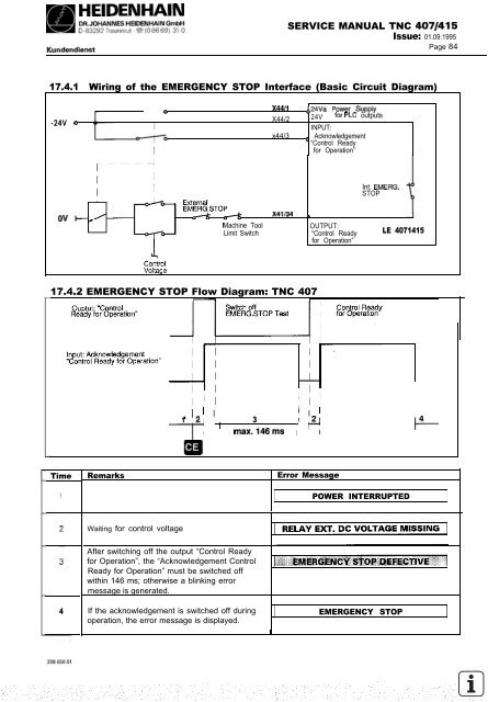
17.4.1 Wiring of the EMERGENCY STOP Interface (Basic Circuit Diagram)<br />
-24V<br />
0<br />
1<br />
0 x44/1<br />
X44/2<br />
,,24& Power supply<br />
24V for PLC outputs<br />
INPUT:<br />
x44/3 ‘ Acknowledgement<br />
“Control Ready<br />
I<br />
for Operation”<br />
x41/34 ,.<br />
17.4.2 EMERGENCY STOP Flow Diagram: <strong>TNC</strong> <strong>407</strong><br />
- I<br />
Time<br />
1<br />
4<br />
1 I<br />
Int. EMERG.<br />
STOP<br />
Machine Tool OUTPUT:<br />
Limit Switch “Control Ready LE <strong>407</strong>1<strong>415</strong><br />
for Operation”<br />
’<br />
1 12 3<br />
/ I<br />
I ’ max.146ms / ?<br />
Remarks Error Message<br />
Waiting for control voltage<br />
After switching off the output “Control Ready<br />
for Operation”, the “Acknowledgement Control<br />
Ready for Operation” must be switched off<br />
within 146 ms; otherwise a blinking error<br />
message is generated.<br />
If the acknowledgement is switched off during<br />
operation, the error message is displayed.<br />
I<br />
POWER INTERRUPTED<br />
EMERGENCY STOP<br />
%


