Service Manual TNC 407 / TNC 415 - heidenhain - DR. JOHANNES ...
Service Manual TNC 407 / TNC 415 - heidenhain - DR. JOHANNES ...
Service Manual TNC 407 / TNC 415 - heidenhain - DR. JOHANNES ...
You also want an ePaper? Increase the reach of your titles
YUMPU automatically turns print PDFs into web optimized ePapers that Google loves.
Kundendienst<br />
HEIDENHAIN<br />
<strong>DR</strong> <strong>JOHANNES</strong> HElDENHAlNGrnbH<br />
D-d3292Tmunreut .%‘(08669) 31-O<br />
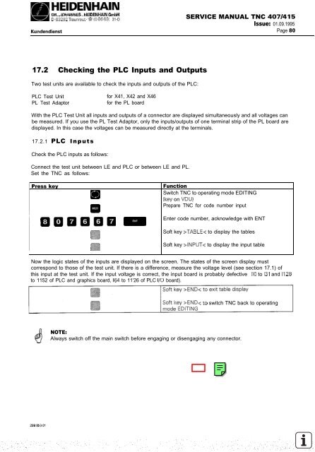
17.2 Checking the PLC Inputs and Outputs<br />
Two test units are available to check the inputs and outputs of the PLC:<br />
PLC Test Unit for X41, X42 and X46<br />
PL Test Adaptor for the PL board<br />
SERVICE MANUAL <strong>TNC</strong> <strong>407</strong>/<strong>415</strong><br />
Issue: 01.09.1995<br />
Page 80<br />
With the PLC Test Unit all inputs and outputs of a connector are displayed simultaneously and all voltages can<br />
be measured. If you use the PL Test Adaptor, only the inputs/outputs of one terminal strip of the PL board are<br />
displayed. In this case the voltages can be measured directly at the terminals.<br />
17.2.1 PLC Inputs<br />
Check the PLC inputs as follows:<br />
Connect the test unit between LE and PLC or between LE and PL.<br />
Set the <strong>TNC</strong> as follows:<br />
Press key Function<br />
Switch <strong>TNC</strong> to operating mode EDITING<br />
w<br />
(key on VDU)<br />
Prepare <strong>TNC</strong> for code number input<br />
m<br />
Enter code number, acknowledge with ENT<br />
000000 =<br />
Soft key >TABLE< to display the tables<br />
Soft key >INPUT< to display the input table<br />
Now the logic states of the inputs are displayed on the screen. The states of the screen display must<br />
correspond to those of the test unit. If there is a difference, measure the voltage level (see section 17.1) of<br />
this input at the test unit. If the input voltage is correct, the input board is probably defective (IO to 131 and 1128<br />
to 1152 of PLC and graphics board, I64 to 11’26 of PLC I/O board).<br />


